


Intel
®
IQ31244 Customer Reference Board
30 User’s Manual
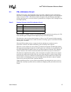
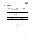
8.0 Jumpers
§ §
Table 22. Jumper Options
Designator Type Configure Description
J4 2-pin post Add shunt to enable
Enables spread-spectrum clocking
on the primary PCI clocks.
J11, J12, J13, J14 3-pin post
Shunt on
Pin 1 and pin 2 = DPA Mode
Pin 2 and pin 3 = Master/Slave
SATA mode selection
J19 3-pin post
Shunt on
Pin 1 and pin 2 = power by switch
Pin 2 and pin 3 = auto power-on
System power by switch
J37 3-pin post
Pin 1 = Cathode
Pin 3 = Anode
Power-on LED
J38 10-pin post JTAG for U30 SATA controller SATA controller JTAG
Z1 2-pin post Chassis “RESET SW” cable Power reset switch
Z2 2-pin post Chassis “PWR SW” cable Power switch
Z3 2-pin post
Open = 100 MHz
Closed = 66 MHz
Primary clock
Z4 2-pin post
Open = PCI-X mode
Closed = PCI mode
PCI-X mode
Z5 2-pin post Add a shunt to the post CompactFlash* to interrupt XINT1#
Z6 2-pin post Add shunt to enable PBI reset mode
Z7 2-pin post Add shunt to enable PBI retry mode
Z12 2-pin post Add shunt to enable Congregated LEDs
Z14 2-pin post Add shunt to enable Buzzer