


Intel
®
IQ31244 Customer Reference Board
24 User’s Manual
5.1 SATA JTAG Interface
The Intel
®
31244 PCI-X to Serial ATA Controller JTAG interface is provided to assist on-board
testing on one of the four 31244 devices. Table 15 shows the pin assignment of the 10-pin header
for the JTAG (J38) on PCI-X to Serial ATA controller (U30).
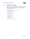
5.2 Intel
®
31244 PCI-X to Serial ATA Controller
Each of the 31244 chips transmits and receives commands to one of the four Serial ATA channels.
Direct Port Access or DPA mode is hard-wired on each of the SATA controllers. DPA mode allows
independent control of the SATA devices, allowing multiple disks to be accessed at the same time.
Refer to the Intel
®
31244 PCI-X to Serial ATA Controller Developer’s Manual (273603) for more
information.
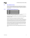
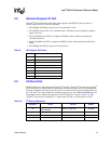
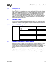
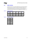
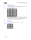
Table 15. SATA JTAG Emulator Pin Assignment
Pin Signal
1TRST#
2GND
3TCK
4GND
5TMS
6GND
7TDI
8GND
9TDO
10 GND
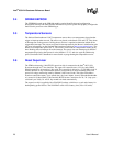
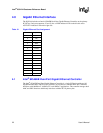
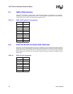
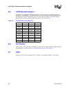
Table 16. SATA Port Pin Assignment
Pin Signal
1Ground
2A+
3A–
4Ground
5B–
6B+
7Ground