4 User’s Manual
Contents
Figures
1Intel
®
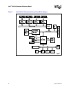
IQ31244 Customer Reference Board Block Diagram.........................................................8
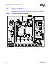
2 Component Layout Diagram (not to scale).................................................................................12
3Intel
®
80321 I/O Processor Block Diagram ................................................................................17
4Intel
®
80321 I/O Processor Interrupt Connections .....................................................................18
5 Peripheral Bus Interface Unit......................................................................................................26
Tables
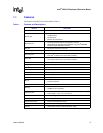
1 Features and Descriptions............................................................................................................ 9
2Intel
®
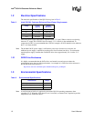
IQ31244 Customer Reference Board Power Requirements.............................................10
3 Environmental Specifications .....................................................................................................10
4 Physical Characteristics ............................................................................................................. 11
5 Documents and Manufacturers ..................................................................................................13
6 Primary PCI Bus.........................................................................................................................14
7 Rotation Scheme of the PAL Arbitration Circuit..........................................................................15
8Intel
®
31154 133 MHz PCI Bridge GPIO Pin Assignments ........................................................18
9 GPIO Signal Definitions.............................................................................................................. 19
10 I
2
C Device Addresses ................................................................................................................ 19
11 Supported SDRAM Configurations.............................................................................................21
12 Gigabit Ethernet Port Assignment ..............................................................................................22
13 SATA Port Assignment...............................................................................................................23
14 SATA Port Pin Assignment.........................................................................................................23
15 SATA JTAG Emulator Pin Assignment.......................................................................................24
16 SATA Port Pin Assignment.........................................................................................................24
17 SATA LED Header ..................................................................................................................... 25
18 Console Serial Port Connector ...................................................................................................27
19 Read-Only Rotary Switch ...........................................................................................................27
20 JTAG Emulator Pin Assignment ................................................................................................. 28
21 ATX Power Connector (J1).........................................................................................................29
22 Jumper Options ..........................................................................................................................30


