


Intel
®
IQ31244 Customer Reference Board
User’s Manual 25
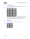
5.3 Activity LEDs
The IQ31244 provides a group of four sets of headers for each SATA controller located on the
bottom-left corner of the board. Each set of headers represents a cathode and anode of an LED for
each port of the SATA controller. The SATA activity can be shown through a LED when it is
connected to the headers. The activity of the SATA controller can displayed in two modes. In DPA
mode, each port has its own LED signal. The group of headers (J16, J17, J18, and J20) are assigned
to each SATA controller (U27, U28, U29, and U30). Z12 is the header for congregated SATA LED
signals. Pin 1 is the cathode and pin 2 is the anode of the LED. The LED symbol is shown on the
board.
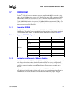
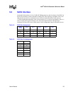
Table 17. SATA LED Header
Pin
Cathode
Pin Anode LED Port
15LED00
26LED11
37LED22
48LED33