


Board Manual 53
Intel® IQ80219 General Purpose PCI Processor Evaluation Platform
Hardware Reference Section
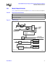
3.10.2 PCIX Initialization Summary
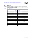
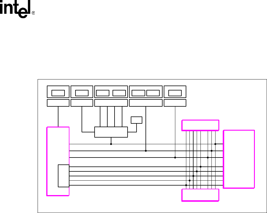
Figure 16 shows a routing guidance on how PCI-X mode is determined/implemented on the
secondary side of the PCI-X bridge. The 80219, GbE device, and the PCI-X expansion slot all reside
on this bus.
3.10.2.1 User Defined Switches
User can set the PCIXCAP signal to force one of the following modes:
The IQ80219 platform is by default set to operate this bus in PCI-X 66 MHz mode. The loading on
the secondary PCI-X bus may result in marginal operation when speed is greater than that.
When an expansion card is placed on the PCI-X expansion slot, the mode is based on the least
capable device on the bus. For example, when the bus is forced to be PCI-X 66 capable and then
places a PCI 66 card in the expansion slot, then the bus is configured as PCI 66.
Important: The clock selection is manually configured. Pay close attention to setting this up correctly.
Important: All settings must be done prior to power-up/reset.
3.10.2.2 PCI-X Bridge Initialization Signals
The On-board PCI-X bridge samples the PCIXCAP, SEL100, and M66EN signals to drive/indicate the
correct mode to the secondary bus devices. The 80219 uses these signals to set its internal PLs,
providing correct frequency to the Intel XScale
®
core, as well as internal, peripheral, and DDR buses.
Figure 16. PCI-X Routing Diagram on Secondary PCI-X Bridge
B2840-01
r
Switch
Sel 100 Enable Selection PCIXCAP M66EN
SPCI-X Slot
82544
Gigabit Ethernet
S8E1-4 S7E1-8 S7E1-6
33 MHz
66 MHz
100 MHz
133 MHz
S7E1-7 S8E2-1 S8E2-2 S8E2-4
Switch
PCI-X Clock
PCIXCAP
M66EN Signal
S_DEVSEL
S_FRAME
S_IRDY
S_STOP
S_TRDY
Switch
OSC
Clock
Multiplier/Buffer
Switch Switch
Intel
®
80219
General
Purpose
PCI
Processor
PCI-X
Bridge
Initialization
Signals
• PCI-X 100/133 • PCI-X 66 • PCI