Board Manual 67
Intel® IQ80219 General Purpose PCI Processor Evaluation Platform
Hardware Reference Section
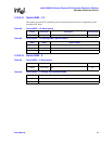
3.10.9.22 Jumper J9E1
Base Address Register Enable:
Used to enable the base address register at reset or power-up. The 64-bit register located at
offsets x'10' and x'14' is used to claim a 1 MB memory region when enabled. The register returns
all zeroes to read accesses and the associated memory region is not claimed when disabled.
0 = (1-2): BAR disabled, register reads returns 0s, no memory region claimed.
1 = (2-3): BAR enabled, bits 63:20 can be written by software to claim a 1 MB memory region.
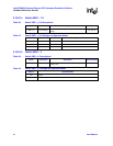
3.10.9.23 Jumper J9F1
Primary Configuration Busy:
Controls the reset and power up value of bit 2 of the miscellaneous control register. Used to
sequence initialization with regard to the primary and secondary buses for applications that
require access to the bridge configuration registers from the secondary bus. When pulled high,
the configuration commands received on the primary bus are retried until such time as bit 2 of
the miscellaneous control register is set to b‘0’ by a configuration write initiated from the
secondary bus. Applications that do not require access to the bridge configuration registers
from the secondary bus pull this signal to ground.
0 = (2-3): Reset value of bit 2 of the miscellaneous control register is b‘0’.
1 = (1-2): Reset value of bit 2 of the miscellaneous control register is b‘1’.
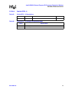
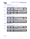
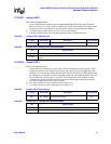
Table 82. Jumper J9E1: Descriptions
Jumper Association Description Factory Default
J9E1 PCI-X Bridge BAR_EN: Enables Base Address Register (BAR) 2-3
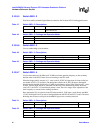
Table 83. Jumper J9E1: Settings and Operation Mode
J9E1 Operation Mode
Pins 1,2 Pulled up. BAR disabled, register reads return 0s, no memory region claimed.
Pins 2,3
Pulled down. BAR enabled, bits 63:20 can be written by software to claim a 1 MB memory
region.
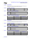
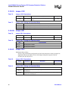
Table 84. Jumper J9F1: Descriptions
Jumper Association Description Factory Default
J9F1 PCI-X Bridge
P_CFG_BUSY: Allows user to control initialization
sequence on the bridge.
2-3
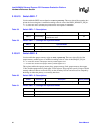
Table 85. Jumper J9F1: Settings and Operation Mode
J9F1 Operation Mode
Pins 1,2 Pulled up. Reset value of bit 2 of the miscellaneous control register to b’0’.
Pins 2,3 Pulled down. Reset value of bit 2 of the miscellaneous control register to b’1’.


