


SBC84833 Series All-In-One Capa Board User’s Manual
JUMPERS AND CONNECTORS
23
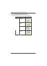
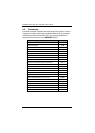
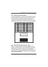
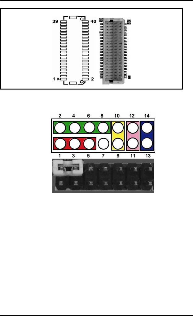
2.4.5 Flat Panel Bezel Connector (CN4)
Power LED
Pin 1 and Pin 5 connect the system power LED indicator with the
corresponding switch on the case. Pin 1 is assigned as +, and Pin 3
& Pin 5 as -. The Power LED lights up when the system is powered
ON. Pin 3 is defined as GND
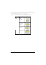
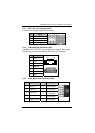
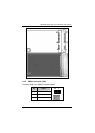
External Speaker and Internal Buzzer Connector
Pin 2, 4, 6 and 8 connect the case-mounted speaker unit or internal
buzzer. While connecting the CPU card to an internal buzzer,
please short pins 2,4; while connecting to an external speaker, you
need to set pins 2,4 to Open and connect the speaker cable to pin 8
(+) and pin 6 (-).
CN3