


SBC84833 Series All-In-One Capa Board User’s Manual
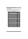
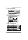
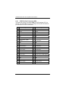
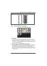
JUMPERS AND CONNECTORS
24
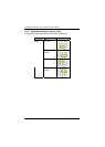
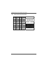
ATX Power On/Off Button
Pin 9 and 10 connect the ATX power button on front panel to the
CPU card, which allows users to control ATX power supply to be
power on/off.
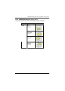
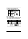
System Reset Switch
Pin 11 and 12 connect the case-mounted reset switch that reboots
your computer without turning OFF the power switch. It is a better
way to reboot your system for a longer life of the system’s power
supply.
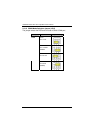
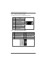
HDD Activity LED
This connection is linked to hard drive activity LED on the control
panel. LED flashes when HDD is being accessed. Pin 13 and 14
connect the hard disk drive to the front panel HDD LED, Pin 13
assigned as -, and Pin 14 as +.