


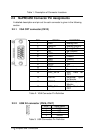
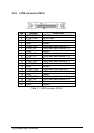
14 • Jumpers and Connectors
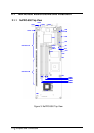
Table 1: Description of Connector Locations
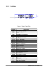
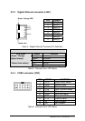
2.2 NuPRO-850 Connector Pin Assignments
A detailed description and pin-out for each connector is given in the following
section.
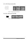
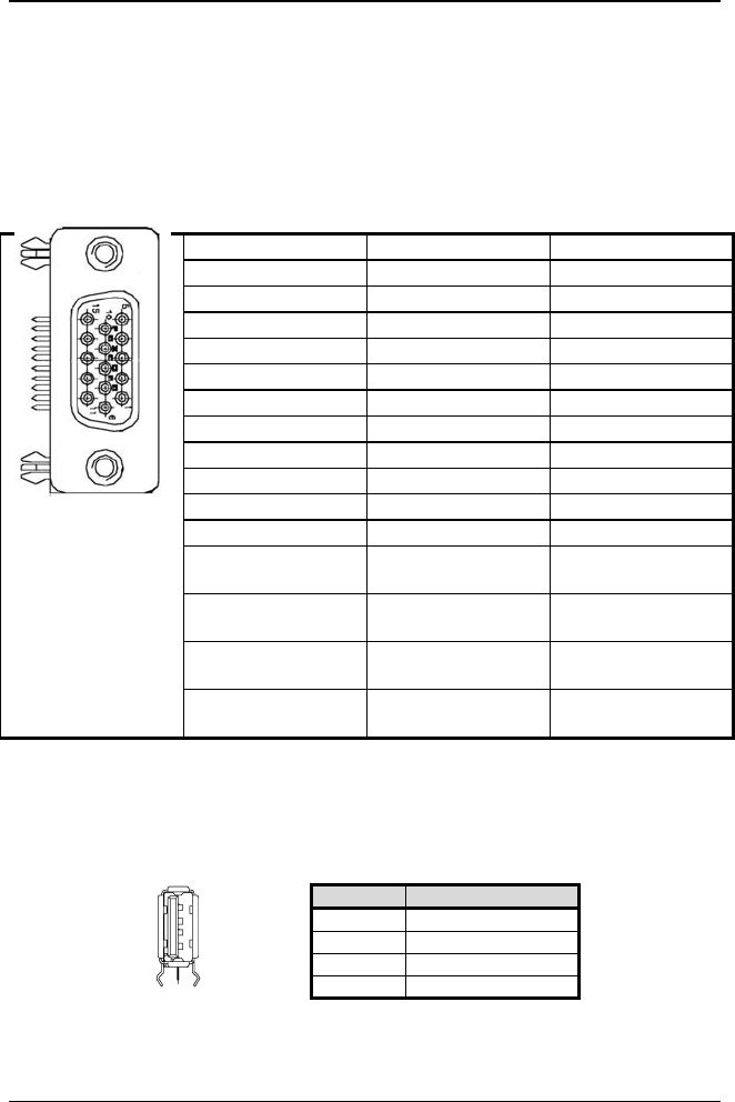
2.2.1 VGA CRT connector (CN13)
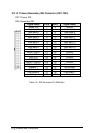
Table 2: VGA Connector Pin Definition
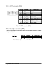
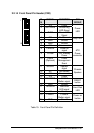
2.2.2 USB 2.0 connector (CN16, CN17)
Pin # Signal Name
1 VCC
2 USB-
3 USB+
4 Ground
Table 3: USB Connectors Pin Definition
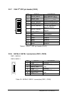
PIN SIGNAL FUNCTION
1
RED Analog RED
2
GREEN Analog GREEN
3
BLUE Analog BLUE
4
NC No Connect
5
GND Ground
6
GND Ground
7
GND Ground
8
GND Ground
9
5VCC +5V
10
GND Ground
11
NC No connect
12
DDC_DATA DDC Data for
CRT
13
HSYNC Horizontal sync
for Monitor
14
VSYNC Vertical sync for
Monitor
15
DDC_CLK DDC Clock for
CRT