


36 • Watchdog Timer
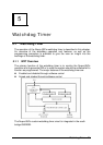
The Intel 6300ESB ICH includes a two-stage Watchdog Timer (WDT) that
provides a resolution that ranging from 1 micro second to 10 minutes. The
timer uses a 35-bit Down-Counter. The counter is loaded with the value from
the first Preload register. The timer is then enabled and starts counting down.
The time at which the WDT first starts counting down is called the first stage. If
the host fails to reload the WDT before the 35-bit down counter reaches zero
the WDT generates an internal interrupt. After the interrupt is generated, the
WDT loads the value from the second Preload register into the WDT’s 35-bit
Down-Counter and starts counting down. The WDT is now in second stage. If
the host still fails to reload the WDT before the second timeout, the WDT drives
the WDT_TOUT# pin low. The WDT_TOUT# pin is held low until the system is
reset.
The WDT of 6300ESB also supports multiple modes, WDT and free-running.
Free-running mode is a one stage timer and it will toggle WDT_TOUT# after
programmable time. WDT mode is a two stage timer and its operation is
described as above.
5.1.2 Configuration Registers
The Intel® 6300ESB ICH WDT, appears to BIOS as PCI Bus 0, Device 29,
Function 4, and has the standard set of PCI Configuration register. The
following describes the configuration registers.
Offset 10H: Base Address Register (BAR)
This register determines the memory base for WDT down-counter setting. It
will be used to set Preload value 1 register, Preload value 2 register, General
Interrupt Status register and Reload register.
Preload Value 1 & 2 registers
These two registers are used to hold the preload value for the WDT timer. Its
value will be automatically transferred into the down-counter every time the
WDT enters the first and second stage. Preload Value 1 register is located at
Base + 00H and Preload Value 2 register is located at Base + 04H. Only bit
[19:0] are settable.
The register unlocking sequence is necessary whenever writing to the Preload
registers. Instructions for writing a value into preload value 1&2 register are as
follows:
1. Write 80H to offset BAR + 0CH.
2. Write 86H to offset BAR + 0CH.
3. Write desired value to preload register. (BAR + 00H or BAR + 04H)