


Evaluation Platform Board Manual 33
Intel
®
IQ80332 I/O Processor
Hardware Reference Section
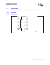
3.6.2 UART
The 80332 has two integrated UARTs. Each asynchronous serial ports supports all the functions of a
16550 UART. The UART signals are connected to a dual RS-232 buffer and then to a RJ-11 serial
port connector mounted on the bracket of the evaluation board. The serial port and GPIO signals are
muxed on the same pins. Jumper J1D2, located next to the serial port buffer can disable the buffer to
allow the signals to be used as GPIO signals. Please see Section 3.9.3, “Jumper Summary” on
page 39 for more details.
3.6.3 Non-Volatile RAM
In addition to the 8MB Flash device, the IQ80332 has a separate 32k by 8 non-volatile RAM device
on the peripheral bus. The NVRAMs address range is from CE87 0000 to CE87 FFFF (in hex).
Please see Section 4.2.2, “Peripheral Bus Memory Map” on page 47 for more details.
3.6.4 Audio Buzzer
The 80332 evaluation board has an audio buzzer that is turned on and off by writing to the Buzzer
Control Register located in the CPLD. Jumper J9D3 adjusts the volume from off, to soft, to loud.
Please see Section 3.9.3, “Jumper Summary” on page 39 for more details. The audio buzzer’s
address range is from CE86 0000 to CE86 FFFF (in hex). Please see Section 4.2.2, “Peripheral Bus
Memory Map” on page 47 for more details.
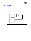
3.6.5 HEX Display
The two pairs of Agilent HDSP-A103 seven segment LEDs are used for displaying POST codes or
other software generated debug codes. Both HEX displays are individually addressed. The left HEX
display address range is CE84 0000 to CE84 FFFF (in hex). The right HEX display address range is
CE85 0000 to CE85 FFFF (in hex). Please see Section 4.2.2, “Peripheral Bus Memory Map” on
page 47 for more details.
3.6.6 Rotary Switch
The 80332 provides a Rotary Switch (S8A1) for the user to select from different boot-up flavors.
Setting ‘0’ enables private devices on the secondary PCI-X bus. Setting ‘0’ allows Redboot to
configure and use devices in slot A. Position ‘1’ allows the host to see all the devices on the
secondary PCI bus. The default setting is position 0. Other settings are currently not validated with
Redboot. Other settings may be used with other software applications. Please see Section 4.2.2,
“Peripheral Bus Memory Map” on page 47 for more details on addressing the rotary switch.
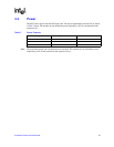
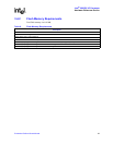
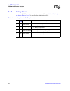
Table 12. Rotary Switch Requirements
Description
Rotary switch has a 4-bit resolution (16 positions).
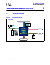
The connection to the peripheral bus is depicted by Figure 7.
Default setting is ‘0’. This enables private devices on PCI-X bus.
Position ‘1’ allows host to see all devices on the secondary bus.