


Intel Core 2 Duo Processor and Intel Q35 Express Chipset—Development Kit Hardware Features
Intel
®
Core
TM
2 Duo Processor and Intel
®
Q35 Express Chipset Development Kit
User’s Manual October 2007
20 Order Number: 318476001US
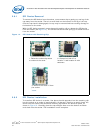
2.7 Debug Features
2.7.1 Extended Debug Probe (XDP)
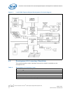
The reference board provides a JTAG-compliant test access port (TAP) for attachment
of an XDP connector. The XDP connector and associated circuitry enable the use of the
ITP for the particular processor to interrupt the boot sequence and view processor
status.
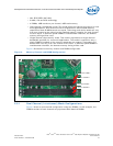
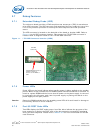
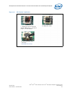
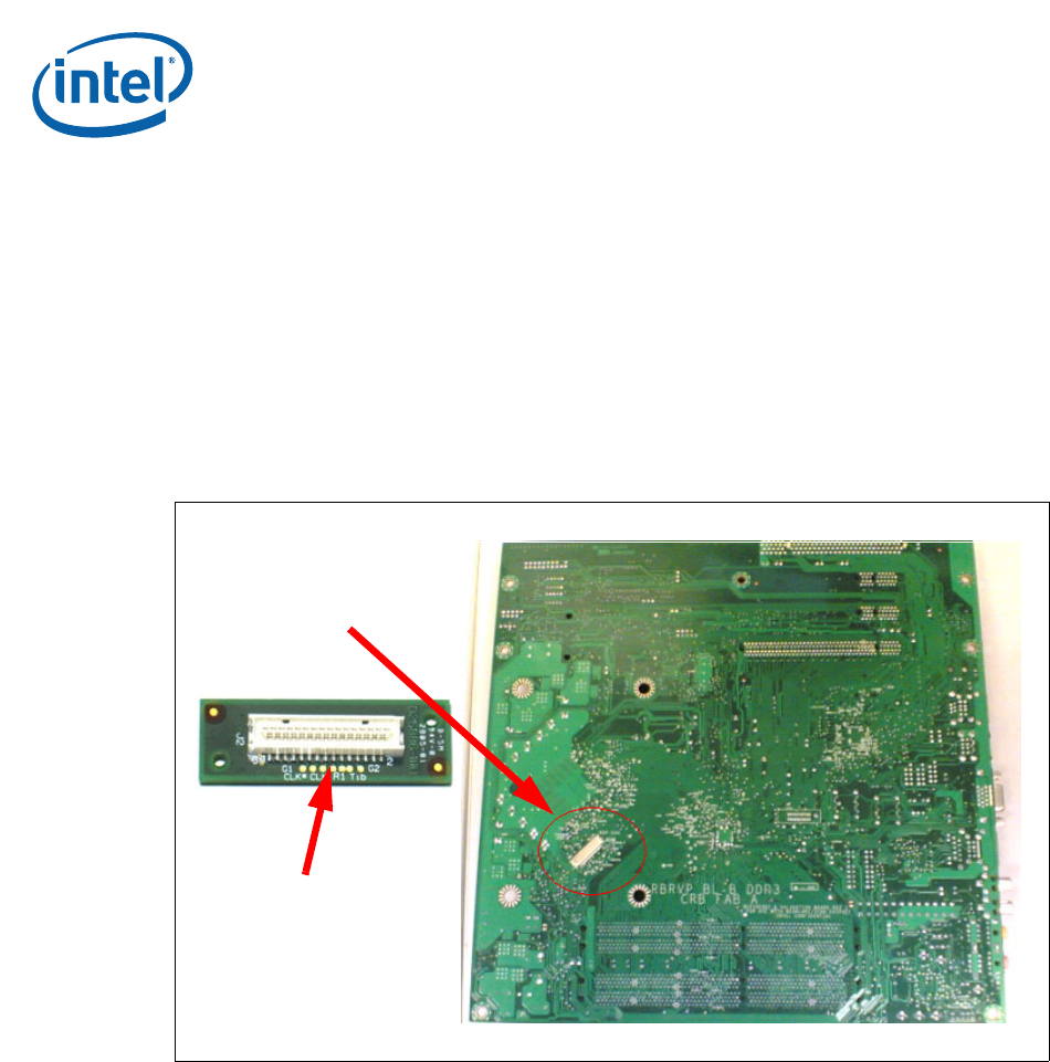
The XDP connector is located on the backside of the board at location J2BC. Refer to
Figure 11 to the XDP connector location. Take notes that ITP-XDP SSA connector is
needed. Refer to diagram below for the ITP-XDP SSA connector.
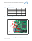
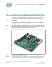
2.7.2 Power LEDs
Power LEDs on the board indicate when standby power is being applied to the standby
planes. When lit they indicate that no DIMM modules should be inserted or removed. To
install or replace DIMM modules insure that AC power to the power supply is removed
by unplugging the AC power cord from the power supply or placing the switch on the
power supply to the open position.
Caution: Removing DIMM modules when the standby power LEDs is lit could result in damage to
the memory devices on those modules.
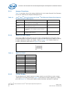
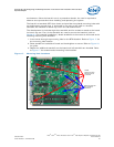
2.7.3 Port 80 POST Code LEDs
Two LEDs display the POST codes output from Port 80 to indicate the progress of the
boot sequence or display the POST code of the last operation successfully completed
during the boot sequence. Please refer to Section 3.4 for more information on Port 80
code reference.
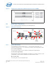
Figure 11. ITP-XDP Connector location (J2BC)
ITP-XDP
Connector
ITP-XDP SSA Connector is
needed in order to
connect to ITP-XDP2/3
tools