


Intel Core 2 Duo Processor and Intel Q35 Express Chipset—Development Kit Hardware Features
Intel
®
Core
TM
2 Duo Processor and Intel
®
Q35 Express Chipset Development Kit
User’s Manual October 2007
24 Order Number: 318476001US
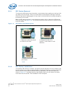
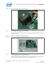
2.9.1 SPI Device Removal
To remove the SPI device from the socket, use a tweezer tip to gently pry one leg of the
cap away from the socket. There is a small latch on the bottom of the leg of the cap.
Once the cap latch is disengaged, the cap may be removed without causing damage to
the latches on the ends.
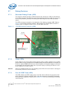
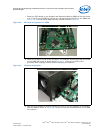
With the SPI device exposed, move the small retaining clip to release the SPI device
from the socket (see Figure 14). The SPI device should now spring up to allow removal
from the socket.
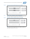
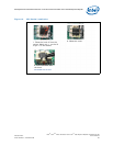
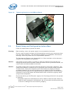
2.9.2 SPI Device Installation
To Install an SPI device in a socket, first place the side opposite from the retaining clip
into the socket at an angle of approximately 15 degrees. Continue to gently insert the
device into the socket until the metal retaining clip latches the device in place, as
shown in Figure 15. Carefully place the cap straight down over the device until both
ends latch into the socket. The installation is now complete.
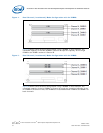
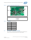
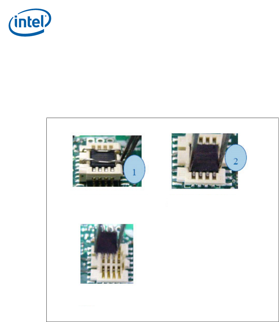
Figure 14. SPI Socket with Retaining Clip
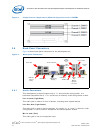
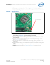
1. Follow the unclench process
to unclench the cover.
2. Clamp the fresh IC at
location 1 and location 2 with
tweezers.
3. Remove the fresh IC from
the socket.