


Intel Core 2 Duo Processor and Intel Q35 Express Chipset—Contents
Intel
®
Core
TM
2 Duo Processor and Intel
®
Q35 Express Chipset Development Kit
User’s Manual October 2007
4 Order Number: 318476-001US
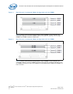
6 Dual Channel (Interleaved) Mode Configuration with 4x DIMMs.......................................17
7 Single Channel (Asymmetric) Mode Configuration with 1x DIMM .....................................17
8 Single Channel (Asymmetric) Mode Configuration with 3x DIMMs....................................18
9 Back-panel Connectors..............................................................................................18
10 LAN Connector LED locations......................................................................................19
11 ITP-XDP Connector location (J2BC) .............................................................................20
12 Major Jumper and Header Locations............................................................................21
13 Location for 1394a Header and USB Front Panel ...........................................................23
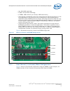
14 SPI Socket with Retaining Clip....................................................................................24
15 SPI Device Installation ..............................................................................................25
16 Intel® Q35 Development Kits ....................................................................................26
17 Mounting Hole Locations............................................................................................27
18 Mounting the Standoff for BTX Heatsink.......................................................................28
19 Casing with “Support and Retention Module” ................................................................28
20 BTX board alignment on SRM .....................................................................................29
21 Heatsink Alignment...................................................................................................29
22 Tightening Heatsink on the SRM and Board..................................................................30
23 CPU Fan location ......................................................................................................31
24 2x12 Standard power supply and 2x2 power supply ......................................................32
Tables
1 Definition ................................................................................................................. 7
2 Intel Literature Centers .............................................................................................. 9
3 Development Kit Hardware Items ...............................................................................12
4 Development Kit Board Specification ...........................................................................13
5 Internal I/O headers .................................................................................................13
6 Supported Intel Technologies .....................................................................................13
7 Additional Features...................................................................................................14
8 LAN Connector LED status .........................................................................................19
9 Voltage Reference detail............................................................................................21
10 Intel
®
Core
TM
2 Duo Processor and Intel
®
Q35 Express Chipset Development Kit Board
Jumpers Description .................................................................................................22
11 USB Front Panel .......................................................................................................22
12 1394a Header ..........................................................................................................23