


Intel
®
Core
TM
2 Duo Processor and Intel
®
Q35 Express Chipset Development Kit
October 2007 User’s Manual
Order Number: 318476-001US 3
Contents—Intel Core 2 Duo Processor and Intel Q35 Express Chipset
Contents
1.0 About This Manual .....................................................................................................6
1.1 Content Overview................................................................................................6
1.2 Text Conventions ................................................................................................6
1.3 Glossary of Terms and Acronyms...........................................................................7
1.4 Support Options..................................................................................................8
1.4.1 Electronic Support Systems .......................................................................8
1.4.2 Additional Technical Support ......................................................................8
1.5 Product Literature ...............................................................................................8
2.0 Development Kit Hardware Features ....................................................................... 10
2.1 Intel® Q35 Express Chipset Development Kit Overview.......................................... 10
2.2 System Block Diagram ....................................................................................... 11
2.3 Development Kit Inventory Checklists .................................................................. 12
2.4 Processor Support ............................................................................................. 14
2.5 System Memory................................................................................................ 14
2.5.1 Dual Channel (Interleaved) Mode Configurations ........................................ 15
2.5.2 Single Channel (Asymmetric) Mode Configurations...................................... 17
2.6 Back-Panel Connectors....................................................................................... 18
2.6.1 Audio-Connectors................................................................................... 18
2.6.2 RJ-45 LAN Connector with Integrated LEDs................................................ 19
2.6.3 USB Port ............................................................................................... 19
2.6.4 Coaxial S/PDIF In/Out Connector.............................................................. 19
2.6.5 eSATA Port............................................................................................19
2.7 Debug Features................................................................................................. 20
2.7.1 Extended Debug Probe (XDP)................................................................... 20
2.7.2 Power LEDs ........................................................................................... 20
2.7.3 Port 80 POST Code LEDs .........................................................................20
2.7.4 Voltage Reference .................................................................................. 21
2.8 Development Kit Major Connectors and Jumpers.................................................... 21
2.8.1 Jumper Functions................................................................................... 22
2.8.2 USB 2.0 Front Panel ............................................................................... 22
2.8.3 1394a Header........................................................................................ 22
2.9 SPI Removal / Installation Technique ................................................................... 23
2.9.1 SPI Device Removal................................................................................ 24
2.9.2 SPI Device Installation ............................................................................24
3.0 Setting Up and Configuring the Development Kit ..................................................... 26
3.1 Overview ......................................................................................................... 26
3.2 Installing Board Standoffs .................................................................................. 26
3.3 BTX Heatsink Setup with SRM ............................................................................. 28
3.3.1 SRM Alignment on any BTX Board ............................................................ 28
3.4 Board Setup and Configuration before Boot........................................................... 30
3.5 Post Codes Definitions........................................................................................ 32
3.5.1 Normal Post Codes ................................................................................. 32
Figures
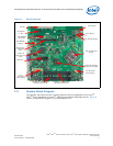
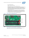
1 Board Features ........................................................................................................ 11
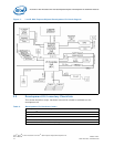
2 Intel® Q35 Express Chipset Development Kit block diagram .......................................... 12
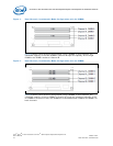
3 Memory Channel and DIMM Configuration ................................................................... 15
4 Dual Channel (Interleaved) Mode Configuration with 2x DIMMs ...................................... 16
5 Dual Channel (Interleaved) Mode Configuration with 3x DIMMs ...................................... 16