


3-8 IQ80960RM/RN
Evaluation Board Manual
Hardware Reference
3.10 User LEDs
The IQ80960RM/RN platform has a bank of eight user-programmable LEDs, located on the upper edge of
the adapter board. These LEDs are controlled by a write-only register and used as a debugging aid during
development. Software can control the state of the user LEDs by writing to the LED Register, located at
E004 0000H. Each of the eight bits of this register correspond to one of the user LEDs. Clearing a bit in the
LED Register by writing a “0” to it turns the corresponding LED “on”, while setting a bit by writing a “1”
to it turns the corresponding LED “off”. Resetting the IQ80960RM/RN platform results in clearing the
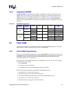
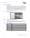
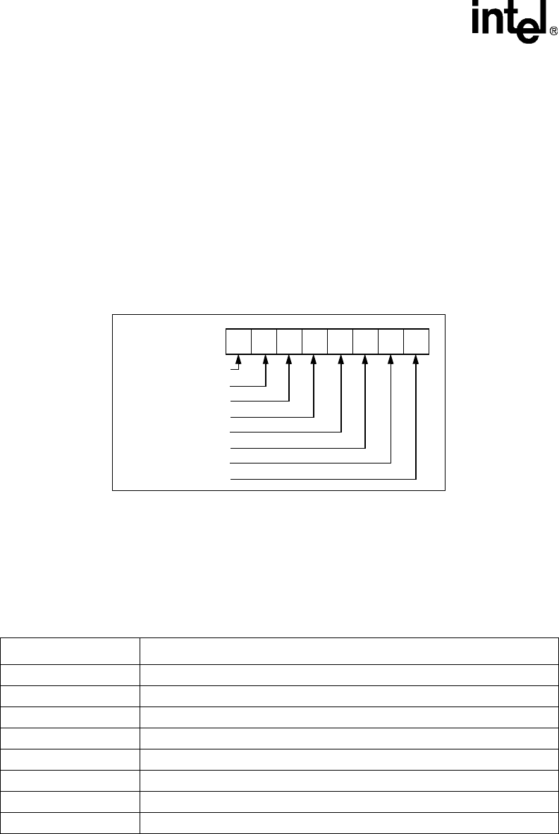
register and turning all the LEDs “on”. The LED Register bitmap is shown in Figure 3-1.
The user LEDs are numbered in descending order from left to right, with LED7 being on the left
when looking at the component side of the adapter.
3.10.1 User LEDs During Initialization
MON960 indicates the progress of its hardware initialization on the user LEDs. In the event that
initialization should fail for some reason, the number of lit LEDs can be used to determine the
cause of the failure. Table 3-10 lists the tests that correspond to each lit LED.
Figure 3-1. LED Register Bitmap
76543210
User LED 7
User LED 6
User LED 5
User LED 4
User LED 3
User LED 2
User LED 1
User LED 0
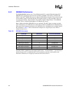
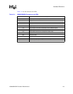
Table 3-10. Start-up LEDs MON960
LEDs Tests
LED 0 SDRAM serial EEPROM checksum validated
LED 1 UART walking ones test passed
LED 2 DRAM walking ones test passed
LED 3 DRAM multiword test passed
LED 4 Hardware initialization started
LED 5 Flash ROM initialized
LED 6 PCI-to-PCI Bridge initialized
LED 7 UART internal loopback test passed