


5-2 IQ80960RM/RN
Evaluation Board Manual
MON960 Support for IQ80960RM/RN
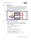
is given the ability to initialize the PCI configuration registers to values other than the default power-up
values. Configuration Mode gives the user maximum flexibility to customize the way in which the i960
RM/RN I/O processor and IQ80960RM/RN platform appear to the PCI host configuration software.
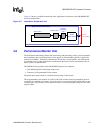
5.2.2 80960JT Core Initialization
The 80960JT core begins the initialization process by reading its Initial Memory Image (IMI) from
a fixed address in the boot ROM (FEFF FF30H in the i960 address space). The IMI includes the
Initialization Boot Record (IBR), the Process Control Block (PRCB), and several system data
structures. The IBR provides initial configuration information for the core and integrated
peripherals, pointers to the system data structures and the first instruction to be executed after
processor initialization, and checksum words that the processor uses in its self-test routine. In
addition to the IBR and PRCB, the required data structures are the:
• System Procedure Table
• Control Table
• Interrupt Table
• Fault Table
• User Stack (application dependent)
• Supervisor Stack
• Interrupt Stack
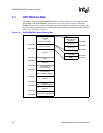
5.2.3 Memory Controller Initialization
Since the i960 RM/RN I/O processor Memory Controller is integral to the design and operation of
the IQ80960RM/RN platform, the operational parameters for Bank 0 and Bank 1 are established
immediately after processor core initialization. Memory Bank 0 is associated with the ROM on the
IQ80960RM/RN platform. Memory Bank 1 is associated with the UART and the LED Control
Register. Parameters such as Bank Base Address, Read Wait States, and Write Wait States must be
established to ensure the proper operation of the IQ80960RM/RN platform. The Memory
Controller is initialized so as to be consistent with the IQ80960RM/RN platform memory map
shown in Figure 4-2.
5.2.4 SDRAM Initialization
SDRAM initialization includes setting operational parameters for the SDRAM controller, and sizing
and clearing the installed SDRAM configuration. To configure the system properly, Presence Detect
data is read from the EEPROM of the SDRAM module, using the 80960RM/RN I
2
C Bus Interface
Unit. Presence Detect data includes the number and size of SDRAM banks present on the installed
module. On power-up, 64 bytes of Presence Detect data are read and validated. The SDRAM
controller is then configured by setting the base address of SDRAM, the boundary limits for each
SDRAM bank, the refresh cycle interval, and the output buffer drive strength. Once the SDRAM
controller is configured, the SDRAM is cleared in preparation for the C language runtime
environment. The actual SDRAM size is stored for later use (e.g., to establish the size of the
IQ80960RM/RN platform PCI Slave image). The SDRAM controller is initialized to be consistent
with the IQ80960RM/RN platform memory map shown in Figure 4-2.