


IQ80960RM/RN
Evaluation Board Manual 4-3
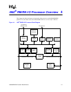
i960® RM/RN I/O Processor Overview
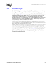
4.2 Local Interrupts
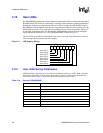
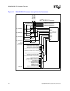
The i960 RM/RN I/O processor is built around an 80960JT core, which has seven external interrupt
lines designated XINT0# through XINT5# and NMI#. In the i960 RM/RN I/O processor, these
interrupt lines are not directly connected to external interrupts, but pass through a layer of internal
interrupt routing logic. Figure 4-3 shows the interrupt connections on the i960 RM/RN I/O processor.
XINT0# through XINT3# on the 80960JT core can be used to receive PCI interrupts from the
secondary PCI bus, or these interrupts can be passed through to the primary PCI interface,
depending on the setting of the XINT Select bit of the PCI Interrupt Routing Select Register in the
i960 RM/RN I/O processor. On the IQ80960RM/RN platform, XINT0# through XINT3# are
configured to receive interrupts from the secondary PCI bus.
XINT4# and XINT5# on the i960 RM/RN I/O processor may be connected to interrupt sources
external to the processor. On the IQ80960RM/RN platform, XINT4# is connected to the loss of fan
detect and XINT5# is connected to the 16C550 UART.
XINT6#, XINT7# receive interrupts from internal sources. NMI# receives interrupts from internal
sources and from an external source. Since all of these interrupts accept signals from multiple
sources, a status register is provided for each of them to allow service routines to identify the
source of the interrupt. Each of the possible interrupt sources is assigned a bit position in the status
register. The interrupt sources for these lines are shown in Figure 4-3. On the IQ80960RM/RN
platform, the NMI# interrupt is not connected to any external interrupt source and receives
interrupts only from the internal devices on the i960 RM/RN I/O processor. Note that all error
conditions result in an NMI# interrupt.