


IQ80960RM/RN Evaluation Platform Board Manual v
Figures
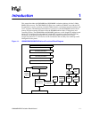
1-1 IQ80960RM/IQ80960RN Platform Functional Block Diagram ...................................................1-1
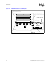
1-2 IQ80960RN Platform Physical Diagram ....................................................................................1-2
3-1 LED Register Bitmap .................................................................................................................3-8
4-1 i960
®
RM/RN I/O Processor Block Diagram..............................................................................4-1
4-2 IQ80960RM/RN Platform Memory Map.....................................................................................4-2
4-3 i960
®
RM/RN I/O Processor Interrupt Controller Connections..................................................4-4
4-4 i960
®
RM/RN I/O Processor DMA Controller ............................................................................4-6
4-5 Application Accelerator Unit.......................................................................................................4-7
Tables
1-1 Document Information ...............................................................................................................1-9
1-2 Cyclone Contacts.......................................................................................................................1-9
3-1 IQ80960RN Platform Power Requirements...............................................................................3-1
3-2 IQ80960RM Platform Power Requirements ..............................................................................3-1
3-3 SDRAM Performance ................................................................................................................3-2
3-4 SDRAM Configurations..............................................................................................................3-3
3-5 UART Register Addresses.........................................................................................................3-4
3-6 Secondary PCI Bus Interrupt and IDSEL Routing .....................................................................3-5
3-7 Logic Analyzer Header Definitions.............................................................................................3-6
3-8 JTAG Header Pinout..................................................................................................................3-7
3-9 Switch S1 Settings.....................................................................................................................3-7
3-10 Start-up LEDs MON960.............................................................................................................3-8
3-11 IQ80960RM/RN Connectors and LEDs .....................................................................................3-9
5-1 Initialization Modes ....................................................................................................................5-3
A-1 IQ80960RN Bill of Materials ..................................................................................................... A-1
A-2 IQ80960RM Bill of Materials..................................................................................................... A-5
B-1 IQ80960RN Schematics List..................................................................................................... B-1
B-2 IQ80960RM Schematics List ....................................................................................................B-2