7 Regulatory and Integration Information..................................................... 93
Product Regulatory Compliance ...........................................................................................93
Product Safety Compliance..........................................................................................93
Product EMC Compliance............................................................................................93
Product Regulatory Compliance Markings...................................................................94
Electromagnetic Compatibility Notices..................................................................................94
FCC (USA) ...................................................................................................................94
INDUSTRY CANADA (ICES-003) ................................................................................95
Europe (CE Declaration of Conformity)........................................................................95
Taiwan Declaration of Conformity ................................................................................ 95
Korean RRL Compliance..............................................................................................96
Australia / New Zealand ...............................................................................................96
Installation Precautions.........................................................................................................96
Installation Requirements......................................................................................................97
Prevent Power Supply Overload .................................................................................. 97
Place Battery Marking ..................................................................................................97
Use Only for Intended Applications..............................................................................97
Figures
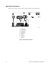
1. Back Panel Connectors ..................................................................................................10
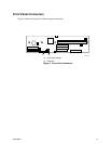
2. Front Panel Connectors ..................................................................................................11
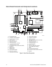
3. Server Board Components..............................................................................................12
4. Location of the Standby Power Indicator LED ................................................................33
5. DIMM Socket Locations .................................................................................................. 44
6. I/O Shield Dimensions.....................................................................................................45
7. Location of the Mounting Screw Holes............................................................................46
8. Installing the Processor in the Processor Socket............................................................47
9. Attaching the Heat Sink to the Processor .......................................................................47
10. Attaching the Fan Heat Sink Clips to the Processor Socket ...........................................48
11. Connecting the Processor Fan Cable to the Processor Fan Connector ......................... 48
12. Removing the Battery......................................................................................................52
13. Connecting the IDE Cable...............................................................................................53
14. BIOS Configuration Jumper Block Location....................................................................54
15. Power and Hardware Control Connectors ...................................................................... 87
16. Add-in Board and Peripheral Interface Connectors ........................................................88
Tables
1. Server Board Features......................................................................................................9
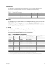
2. Supported Processors ....................................................................................................13
3. Supported Memory Configurations ................................................................................. 13
4. Supervisor and User Password Functions......................................................................25
5. Effects of Pressing the Power Switch .............................................................................29
6. Power States and Targeted System Power ....................................................................29
7. Wake-up Devices and Events.........................................................................................30
8. Fan Connector Function/Operation.................................................................................32
9. PCI Bus Characteristics .................................................................................................. 35
10. PCI Bus Configuration IDs ..............................................................................................35
vi Intel Server Board S845WD1-E Product Guide


