


4
HARDWARE INSTALLATION
1 HARDWARE INSTALLATION
Using the included RJ45 Ethernet cable (and more, as needed), make
your 4-Port Broadband Router network connections by following the
steps below and referring to the Port and LED descriptions (presented
from left to right).
1. Turn off all devices to be incorporated into the network, including
any PCs, switches/hubs, the modem and the router.
2. Connect the LAN or Ethernet network port of the cable/DSL modem
to the router’s WAN port.
3. Connect PCs (and any switch/hub used to expand the network) to
the router’s LAN ports.
4. Turn on the cable/DSL modem.
5. Use the included power adapter to connect the router to an AC
outlet.
6. Turn on the PC you’ll be using to congure the router.
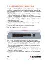
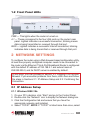
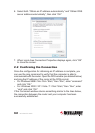
1.1 Rear Panel Ports & Jacks
WAN — This 10/100Mbps port connects the cable/DSL modem.
PC1-4 — These four LAN ports connect networked devices, such as
PCs, print servers and remote hard drives. If you connect a LAN
port to a switch or hub, check that both the device’s Power LED
and the router’s corresponding PC/LAN LED (see below) light to
conrm the connection.
Reset — Push this recessed button to clear all established router
conguration settings and reset to the factory default settings. See
Section 3: Restore Defaults.
PWR — This jack is for the included external 9 V DC, 500 mA power
adapter.
PWR
PC2
PC3
PC4
Reset
WAN
PC1