


Chapter 2 Hardware Installation and Connection
ES-1528 User’s Guide
32
" Do NOT block the ventilation holes. Leave space between devices when
stacking.
For proper ventilation, allow at least 4 inches (10 cm) of clearance at the front
and 3.4 inches (8 cm) at the back of the switch. This is especially important for
enclosed rack installations.
2.2 Mounting the Switch on a Rack
This section lists the rack mounting requirements and precautions and describes the
installation steps.
2.2.1 Rack-mounted Installation Requirements
• Two mounting brackets.
• Eight M3 flat head screws and a #2 Philips screwdriver.
• Four M5 flat head screws and a #2 Philips screwdriver.
" Failure to use the proper screws may damage the unit.
2.2.1.1 Precautions
• Make sure the rack will safely support the combined weight of all the equipment it
contains.
• Make sure the position of the switch does not make the rack unstable or top-heavy. Take
all necessary precautions to anchor the rack securely before installing the unit.
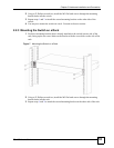
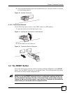
2.2.2 Attaching the Mounting Brackets to the Switch
1 Position a mounting bracket on one side of the switch, lining up the four screw holes on
the bracket with the screw holes on the side of the switch.
Figure 6 Attaching the Mounting Brackets