


Chapter 3 Hardware Overview
ES-1528 User’s Guide
38
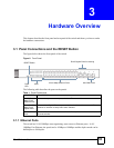
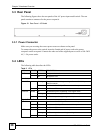
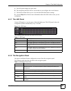
3.3 Rear Panel
The following figures show the rear panels of the AC power input model switch. The rear
panel contains a connector for the power receptacle.
Figure 13 Rear Panel - AC Model
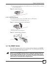
3.3.1 Power Connector
Make sure you are using the correct power source as shown on the panel.
To connect the power to the switch, insert the female end of power cord to the power
receptacle on the rear panel. Connect the other end of the supplied power cord to a 100~240V
AC, 1.5A power outlet.
3.4 LEDs
The following table describes the LEDs.
Table 2 LEDs
LED COLOR STATUS DESCRIPTION
PWR Green On The system is turned on.
Off The system is off.
10/100 Mbps Ethernet Ports
LNK/ACT Amber Blinking The system is transmitting/receiving to/from a 10/100 Mbps
Ethernet network.
On The link to a 10/100 Mbps Ethernet network is up.
Off The link to an Ethernet network is down.
FDX/COL Amber On The Ethernet port is negotiating in full-duplex mode.
Blinking The switch is detecting collisions on the Ethernet port.
Off The Ethernet port is negotiating in half-duplex mode.
Gigabit Ethernet Ports
100/1000 Green On The link to a 10/1000 Mbps Ethernet network is up.
Amber On The link to a 100 Mbps Ethernet network is up.
Off The link to an Ethernet network is down.
ACT Green On The link to an Ethernet network is up.
Blinking The Ethernet port is transmitting/receiving data.
Off The link to an Ethernet network is down.