


Chapter 4 The Web Configurator
ES-1528 User’s Guide
45
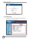
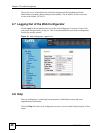
A - The LED panel displays the port status.
B - The navigation panel has links to screens that let you configure the switch features.
C - The function frame allows you to view and edit individual feature settings.
D - Use the Help link to find out more information about the fields in the screen you are
configuring.
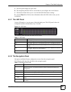
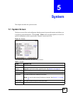
4.3.1 The LED Panel
Use the LED panel to view the status of the individual ports. The LED panel in the web
configurator updates automatically every 5 seconds.
Figure 16 LED Panel
The following table describes the labels in this screen.
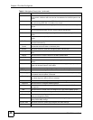
4.3.2 The Navigation Panel
Navigate to individual feature configuration screens from the navigation panel.
The following table describes the links in the navigation panel.
Table 3 LED Panel
LABEL DESCRIPTION
1G This LED is green if the corresponding port has a 1 Gbps connection.
100 This LED is green if the corresponding port has a 100 Mbps connection.
Full This LED is green if the corresponding port is transmitting in full duplex
mode.
Link This LED is green if the corresponding port has an Ethernet connection. It
is orange if the port has been disabled.
1...28 This number indicates the port number on the switch.
Table 4 Navigation Panel Links
LINK DESCRIPTION
System Use these screens to view general system information such as firmware version, IP
address and so on. You can also use this screen to backup and restore your
configuration.
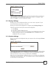
Status Use this screen to view general system and hardware monitoring information.
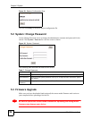
Password Use this screen to change the system login password
Firmware Use this screen to perform firmware upgrades
Restart/
Reset
Use this screen to reboot the switch or to restore the default configuration of the
switch.
Port Use these screens to view the status and configure settings for individual ports on
the switch.