


Front Panel 11
Front Panel
This section describes the following elements on the front panel of an SSG 20
device:
System Status LEDs
Port Descriptions
Mini Physical Interface Module Port Descriptions
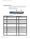
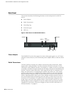
System Status LEDs
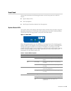
The system status LEDs display information about critical device functions. Figure 3
illustrates the position of each status LED on the front of the SSG 20-WLAN device.
The WLAN LEDs are only present on the SSG 20-WLAN device.
Figure 3: Status LEDs
When the system powers up, the POWER LED changes from off to blinking green,
and the STATUS LED changes in the following sequence: red, green, blinking green.
Startup takes approximately two minutes to complete. If you want to turn the
system off and on again, we recommend you wait a few seconds between shutting
it down and powering it back up. Table 2 provides the name, color, status, and
description of each system status LED.
Table 2: Status LED Descriptions
Name Color Status Description
POWER Green On steadily Indicates that the system is receiving power.
Off Indicates that the system is not receiving
power.
Red On steadily Indicates that the device is not operating
normally.
Off Indicates that the device is operating
normally.
STATUS Green On steadily Indicates that the system is starting or
performing diagnostics.
Blinking Indicates that the device is operating
normally.
Red Blinking Indicates that there is an error detected.
PIM 1 Green On steadily Indicates that the mini PIM is functioning.
Blinking Indicates that the mini PIM is passing traffic.
Off Indicates that the mini PIM is not
operational.
STATUS
POWER
PIM 2
PIM 1
b/g
802.11a
WLAN
12