


Connectors 61
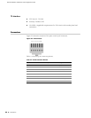
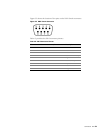
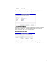
Figure 23 shows the location of the pins on the DB-9 female connector.
Figure 23: DB-9 Female Connector
Table 12 provides the DB-9 connector pinouts.
Table 12: DB-9 Connector Pinouts
Pin Name I/O Description
1DCD I Carrier Detect
2RxD I Receive Data
3TxD O Transmit Data
4 DTR O Data Terminal Ready
5 GND N/A Signal Ground
6 DSR I Data Set Ready
7RTS O Request To Send
8CTS I Clear To Send
9RING I Ring Indicator