


10
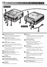
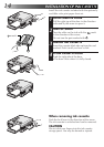
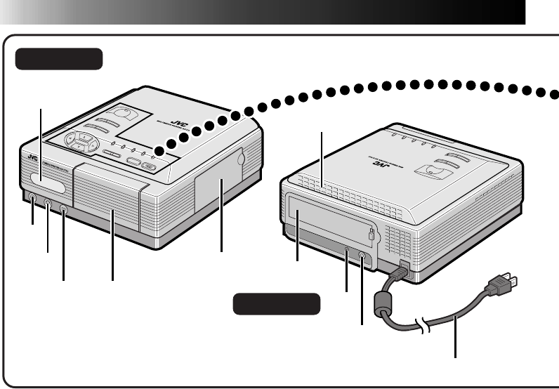
Rear View
CONTROLS, INDICATORS AND CONNECTORS
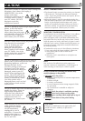
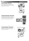
Front View
1 IrDA (IrTran-P) sensor
•Receives video data through the IrDA
(IrTran-P) communication system.
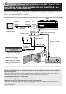
2 VIDEO INPUT connector
•Connect to the source unit’s normal
video output using the provided video
cable.
3 S-Video INPUT connector
•Connect to the source unit’s S-Video
output using the provided S-Video cable.
4 DV IN connector
•Used to receive video data from a digital
camcorder with a DV connector using
the provided DV cable.
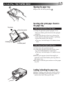
5 Paper Tray Access Door
•Open this to insert the paper tray.
6 Ink Cassette Access Door
•Open this to load or unload the ink
cassette.
7 POWER button
•Turns the printer on and off.
8 PICTURE PROCESSOR button
•Press to use the Picture Processor
function.
9 OK button
•Press to enter menu settings.
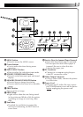
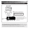
1
e
r
t
y
u
4
5
3
2
6
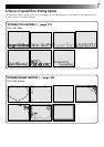
0 DV lamp
•Lights when a source unit’s DV output is
connected to the DV IN connector using
the provided DV cable and the DV
mode is selected.
! IrDA (IrTran-P) lamp
•Lights when receiving video data
through the IrDA (IrTran-P)
communication system from an IrDA-
compatible digital camcorder.
@ VIDEO lamp
•Lights when a source unit’s video output
is connected to the VIDEO INPUT
connector using the provided video
cable and the VIDEO mode is selected.
# PC lamp
•Lights when a computer is connected to
the PC connector and the PC mode is
selected for manipulation of printer
images.
$ EXACT FRAME lamp
•Lights when the EXACT FRAME button is
pressed to use the Exact Frame function.
% EXACT FRAME button
•Press to use the Exact Frame function.