


22
About the external control
This monitor has three external control terminals.
● Make/Trigger terminal (RJ-45): The following external control
systems are available.
(1) Make (make contact) system:
Controls the monitor by short-circuiting the corresponding pin
terminal to the GND pin terminal, or disconnecting (opening) it.
(2) Trigger (trigger) system:
Controls the monitor by sending the pulse signal instantaneously
to the corresponding pin terminal.
☞ “Using the Make/Trigger system” below
● RS-485 terminals (RJ-45): Controls the monitor with the RS-485
system (☞ “Using the serial communication” on page 23).
● RS-232C terminal (D-sub 9-pin): Controls the monitor with the
RS-232C system (☞ “Using the serial communication” on page 23).
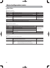
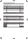
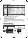
Set the following items of “Remote Setting” in Set-Up Menu
according to the external control terminal and control system (☞
“Serial Type,” “Parallel Type” on page 18).
Control
terminal
Control system
The settings of this unit
“Serial Type”
setting
“Parallel
Type” setting
Make/
Trigger
terminal
Parallel Type Make — Make
Trigger — Trigger
RS-485
terminal
Serial
communication
RS-485
RS485*
1
—
RS-232C
terminal
RS-232C
RS232C*
1
—
*
1
For a monitor connected to a personal computer etc, select the
terminal the equipment is actually connected to. For other monitors,
select “RS485.”
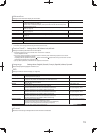
Control priority is as follows.
Make > Trigger = serial communication = buttons and menu on
the monitor
● You can use external control even when “Control Lock” is set to
“Volume Lock” or “All Lock” (☞ page 19).
● When the monitor is off (on standby), external control is not
available. But certain external controls (starting/terminating
communication, turning on the monitor) are available through the
serial communication (☞ page 24).
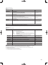
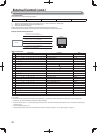
<Make/Trigger system>
You can control the monitor by a personal computer or dedicated
controller*
2
.
● “Using the Make/Trigger system” below.
*
2
The controller is not commercially available. Consult your dealer if
you need it.
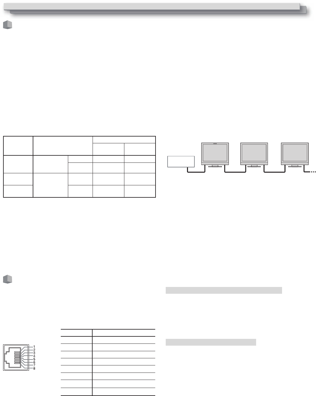
<Serial communication>
RS-485 IN
or
RS-232C
RS-485
OUT
RS-485
IN
RS-485
OUT
RS-485
IN
RS-485
OUT
●
For the details, see page 23.
PC, etc.
External Control
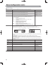
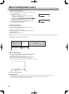
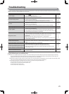
Using the Make/Trigger system
The Make/Trigger terminal is configured as follows. You can assign a
function to each pin terminal in “Remote Setting” (☞ “Pin1, Pin2, Pin3,
Pin4, Pin5” in “Parallel Type” on page 18).
● You cannot change the functions assigned to the pin terminals
from 6th to 8th.
Pin No. Pin name
1 Pin1
2 Pin2
3 Pin3
4 Pin4
5 Pin5
This is a female terminal. 6 Tally*
1
7 Enable*
2
8 GND
*
1
The 6th pin terminal controls turning on or off the tally lamp
(available to control even when the 7th pin terminal is invalid).
*
2
The 7th pin terminal makes the external control valid/invalid. Make
sure to control the terminal by the Make system.
To assign the functions to the pin terminals
For the operation procedure, see page 12.
1 Select “Remote Setting” on the Set-Up Menu.
2 Set “Parallel Type” to “Set.”
3 Select a pin name (“Pin1” – “Pin5”) for which you want to assign a
function, then select the function you want to assign.
For the selectable functions, see the table on page 23.
Operation of the external control
1 Set “Parallel Type” of “Remote Setting” to “Make” or “Trigger” in the
Set-Up Menu.
2 Short-circuit the 7th pin terminal (ENABLE) to the 8th pin terminal
(GND) so that the monitor can be controlled by the external control.
3 When the “Make” system is selected: Operate each function by short-
circuiting the corresponding pin terminal to the 8th pin terminal
(GND) or opening it.
When the “Trigger” system is selected: Operate each function by
pulse control, that is short-circuiting the corresponding pin terminal
to the 8th pin terminal (GND) for about 1 second and opening it.
●
When changing the input with Make system, activate the pin you
want after deactivating the currently used pin.
● When selecting the “Trigger” system, you can operate only one
function at a time. Operate the functions one by one.