


30
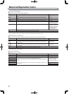
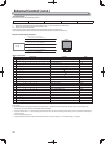
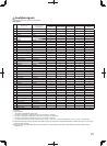
Computer signals (preset)
Analog RGB input (COMP./RGB terminals) and DVI input (HDMI terminal):
No. Signal name
Resolution Frequency
Scan system
Horizontal Vertical Horizontal (kHz) Vertical (Hz)
1 VGA60 640 480 31.5 59.9 Non-interlace
2 WVGA60 852 480 31.5 59.9 Non-interlace
3 SVGA60 800 600 37.9 60.3 Non-interlace
4 XGA60 1024 768 48.4 60.0 Non-interlace
5 WXGA (1280) 1280 768 47.8 60.0 Non-interlace
6 WXGA+60 1440 900 55.9 60.0 Non-interlace
7 SXGA60 1280 1024 64.0 60.0 Non-interlace
8 UXGA60 *
1
1600 1200 75.0 60.0 Non-interlace
9 WUXGA60 *
1
1920 1200 74.0 60.0 Non-interlace
10 1080/60p 1920 1080 67.5 60.0 Non-interlace
11 1080/50p 1920 1080 56.3 50.0 Non-interlace
12 US TEXT *
2,
*
5
720 400 31.5 70.1 Non-interlace
13 WXGA(1360) 1360 768 47.7 60.0 Non-interlace
14 SXGA+/60A *
3
1400 1050 64.0 60.0 Non-interlace
15 SXGA+/60B *
4
1400 1050 65.2 60.0 Non-interlace
16 MAC13
*
5
640 480 35.0 66.7 Non-interlace
17 MAC16
*
5
832 624 49.7 74.5 Non-interlace
18 MAC19
*
5
1024 768 60.2 74.9 Non-interlace
19 MAC21
*
5
1152 870 68.7 75.1 Non-interlace
*
1
No. 8 and No. 9 signals come in, thin lines will become obscured because their signal resolution is higher than the screen resolution.
*
2
The signal is recognized as VGA400/70, and the status is displayed as “VGA400/70”.
*
3
The signal is recognized as SXGA+60, and the status is displayed as “SXGA+60”.
*
4
The signal is recognized as SXGA+60*, and the status is displayed as “SXGA+60*”.
*
5
Only supports analog RGB input.
●
Non-preset signals may not be displayed normally even if the frequency is within the acceptable range.
● When a preset signal comes in, the signal format is shown on the status display. When a non-preset signal comes in, “Out Of Range” appears.
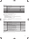
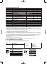
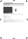
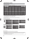
Specification of the HDMI terminal
Connect it to the HDMI output terminal of a video device.
Pin No. Input signal Pin No. Input signal Pin No. Input signal
1 T.M.D.S Data 2+ 8 T.M.D.S Data 0 shield 15 SCL
2 T.M.D.S Data 2 shield 9 T.M.D.S Data 0– 16 SDA
3 T.M.D.S Data 2– 10 T.M.D.S Clock+ 17 DDC/CEC GND
4 T.M.D.S Data 1+ 11 T.M.D.S Clock shield 18 +5 V Power
5 T.M.D.S Data 1 shield 12 T.M.D.S Clock– 19 Hot Plug Detect
6 T.M.D.S Data 1– 13 CEC
7 T.M.D.S Data 0+ 14 Spare (not connected)
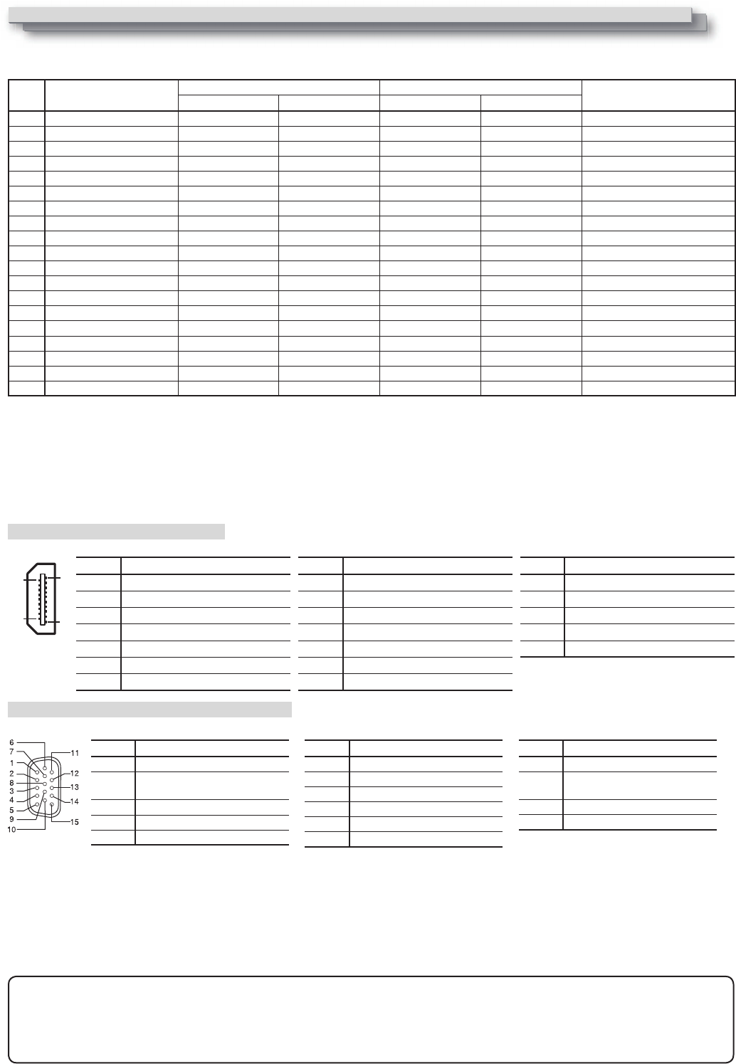
Specification of the mini D-SUB15pin terminal
Connect it to the mini D-SUB15pin output terminal of a video device.
Notice on transportation
This monitor is precision equipment and needs dedicated packing material for transportation.
Never use any packing material supplied from sources other than JVC or JVC-authorized dealers.
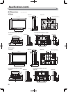
● For easy understanding, pictures and illustrations are shown by being emphasized, omitted or composed, and may be slightly different
from actual products.
● Design and specifications are subject to change without notice.
● All company names and product names mentioned herein are used for identification purposes only, and may be the trademarks or
registered trademarks of their respective companies.
Pin No. Input signal
1 Red video signal
2
Green video signal or Sync on
Green signal
3 Blue video signal
4 Not connected
5 Ground
Pin No. Input signal
6 Red video signal return
7 Green video signal return
8 Blue video signal return
9 Not connected
10 Ground
11 Not connected
Pin No. Input signal
12 I2C data
13
Horizontal or Composite
synchronization signal
14 Vertical synchronization signal
15 I2C clock
Specifications (cont.)