6
Daily Operations / Connections
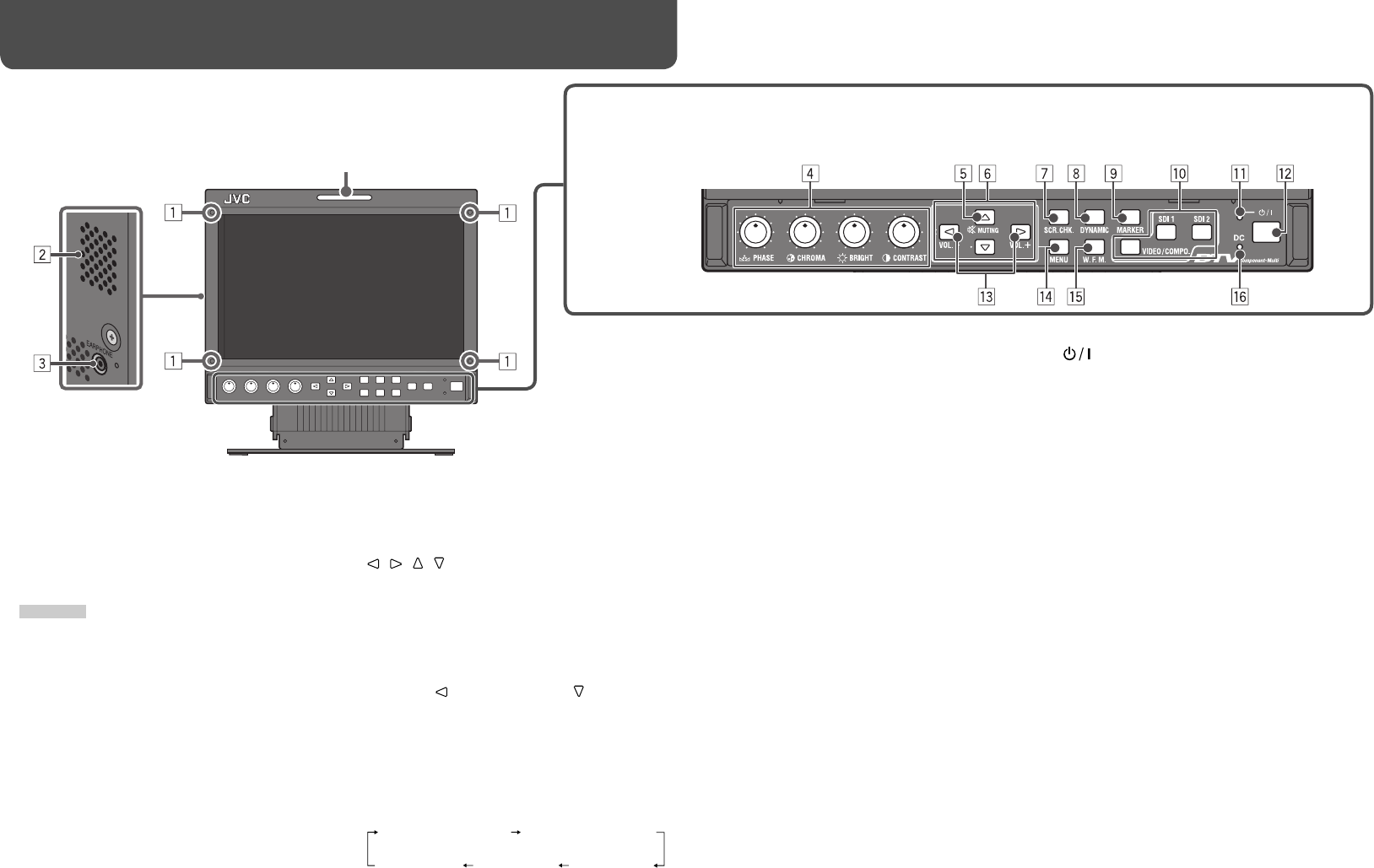
7 Front panel
8 DYNAMIC button/lamp
Adjusts the picture to be suitable for a bright place.
• When the DYNAMIC lamp lights:
– “BACK LIGHT” and “PICTURE SUB ADJ.” are
not displayed on the menu.
– The setting of “BACK LIGHT” is ineffective.
(☞ page 10, 14)
9 MARKER button/lamp
Displays/hides the area marker and the safety
marker.
• Select the size and the style of the markers in
“MARKER” of the MAIN MENU (☞ page 11).
• The marker is not displayed when it is set to
“OFF” in “MARKER.” (☞ “NOTE” on page 11)
p Input select buttons/lamps
Selects an input.
VIDEO/COMPO.: VIDEO/COMPONENT terminal
SDI 1: E. AUDIO HD/SD SDI (IN 1) terminal
SDI 2: E. AUDIO HD/SD SDI (IN 2) terminal
• The lamp for the selected input lights.
• Select an appropriate setting of “VIDEO/COMPO.
SEL.” (☞ page 10).
q Power lamp
Unlit: The monitor is completely off (both the
POWER switch and DC switch on the rear panel
are turned off).
Lights in green: The monitor is on.
Lights in orange: The monitor is off (on standby).
Flashes in orange: The monitor is in the P. SAVE
(power save) mode (☞ “NO SYNC ACTION” in
“SYNC FUNCTION” on page 13).
w button
Turns on and off (on standby) the monitor.
• The power switches (the POWER switch and
DC switch) are equipped on the rear panel of the
monitor (☞ 1, 3 on page 8).
• To turn off the monitor completely, turn off the
POWER switch and DC switch.
e VOL. +/– buttons
Adjusts the volume.
r MENU button
Activates/deactivates the display of the MAIN MENU.
(☞ “Menu Operations” on page 7)
t W. F. M. (Wave form monitor) button/lamp
Displays/hides the indication of the wave form
monitor.
• Adjust the settings of the wave form monitor in
“WAVE FORM SETTING” of the MAIN MENU
(☞ page 13).
• Closed captions (☞ page 13) disappear when the
wave form monitor is displayed.
y DC lamp
When the DC 12 V power voltage is being lowered
due to the battery consumption, the lamp changes
to orange from green. When the voltage becomes
lower than a certain level, the monitor automatically
turns off and the lamp turns to red.
• Make sure to turn off the POWER switch and
DC switch on the rear panel before replacing the
battery.
• The length of time that the lamp lights in orange
differs depending on the type of battery or the
battery condition. It is recommended to replace
the battery when the lamp turns to orange.
Tally lamp
This lamp is controlled by the tally function of the MAKE/TRIGGER terminal.
• This lamp can also be used as the format indicator (☞ “FORMAT
INDICATOR” in “FUNCTION SETTING” on page 14).
• “NO EFFECT” is displayed when you press a button which is not available for the current input or signal format (the lamp
lights even when the function does not actually work).
• The items controlled by the MAKE system cannot be controlled by the buttons on the front panel (“REMOTE ON” is displayed
and the lamps do not light).
5 MUTING button
Turns off the sound when no menu screen is
displayed.
• To cancel the function, press the button again or
press VOL. +/– buttons.
6 / / / buttons
When a menu screen is displayed
Selects or adjusts menu items. (☞
“Menu
Operations” on page 7)
When no menu screen is displayed
Selects the audio channels of EMBEDDED AUDIO
signals, or adjusts the volume. (☞ “Audio Channel
Selection” on page 7)
• Pressing button while holding button displays
the SET-UP MENU. (☞ “Menu Operations” on
page 7)
7 SCR. CHK. (Screens check) button/lamp
Displays only the selected element (R, G, B, or the
luminance) of video signal.
• Each time you press this button, the screen
changes in the following order.
1 Screw holes for attaching protective filter
(provided)
• Attach the protective filter by using the provided
screws.
• Attach the filter to the LCD panel with the frosted
side of the filter facing outwards (when shipped
from the factory, a protective film and a sticker
are attached to the frosted side).
CAUTION
• Use only the provided screws to avoid damaging the
monitor.
• When attaching the protective filter, do not fasten
screws too tightly; otherwise, the protective filter may
be damaged.
2 Speaker (monaural)
The speaker emits the same audio signal as
emitted from the AUDIO (MONITOR OUT) OUT 1
terminal. (☞ “9 AUDIO (MONITOR OUT) terminals”
on page 8)
3 EARPHONE (earphones) jack (monaural)
Connect earphones to this jack to listen to the same
sound as produced from the speaker.
4 Picture adjustment knob
PHASE: Adjusts the picture hue.
CHROMA: Adjusts the picture color density.
BRIGHT: Adjusts the picture brightness.
CONTRAST: Adjusts the picture contrast.
Normal screen
Red screenGreen screenBlue screen
Monochrome screen
DT-V9L3D_J_en.indb 6DT-V9L3D_J_en.indb 6 09.8.7 1:30:27 PM09.8.7 1:30:27 PM


