


17
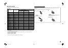
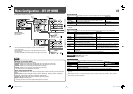
Operation of the external control
1 Set “TYPE SEL.” of “REMOTE SETTING” to “MAKE” or “TRIGGER” in the SET-UP MENU.
2 Short-circuit the 7th pin terminal (ENABLE) to the 8th pin terminal (GND) so that the monitor can be controlled
by the external control.
3 When the “MAKE” system is selected: Operate each function by short-circuiting the corresponding pin terminal
to the 8th pin terminal (GND) or opening it.
When the “TRIGGER” system is selected: Operate each function by pulse control, that is short-circuiting the
corresponding pin terminal to the 8th pin terminal (GND) for about 1 second and opening it.
• When changing the input with MAKE system, only one pin terminal must be short-circuited. (Other pin terminals
must be opened.)
• When selecting the TRIGGER system, you can operate only one function at a time. Operate the functions one
by one.
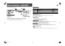
7 Using the RS-232C system
You can control the monitor from a personal computer etc. via the RS-232C terminal.
• Consult your dealer for the details of the external control specification.
<Communication specifications>
Baud Rate: 4800 bps
Data Bits: 8 bits
Parity: No parity
Stop Bits: 1 bit
Flow Control: No control
Communication Code: ASCII Code
• Use a straight cable with a D-sub 9-pin connector (male for the monitor, female for the personal computer).
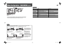
<Command outline>
All commands consist of the following segments.
Header Monitor ID (00) Command ID Function Data
Cr (0Dh)
Header
“!”: Operation commands from the personal computer, etc. For details, see <Basic command list> on the right.
“?”: Reference commands from the personal computer, etc.
“@”: Status returns from the monitor
• To start communication, send the connection command from the personal computer etc.
• To terminate the communication, send the termination command from the personal computer etc.
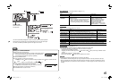
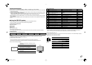
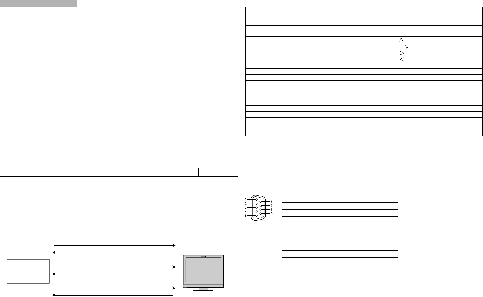
Example of communication procedures
1 Starting the communication: connection command
(!00BCN1Cr)
3 Selecting “SDI 1” input (!00BINACr)
5 Terminating the communication: termination command
(!00BCN0Cr)
6 Monitor’s status (@00BOKCr)
4 Monitor’s status (@00BOKCr)
2 Monitor’s status (@00BOKCr)
PC, etc.
Monitor
This is a female
terminal.
Pin No. Signal
1
NC
2
RXD
3
TXD
4
NC
5
GND
6
NC
7
RTS
8
CTS
9
NC
• The 7th terminal and the 8th terminal are connected.
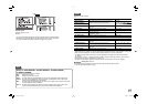
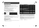
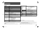
<Basic command list>
No. Commands Functions Data
1 ! 0 0 B C N 1 Cr Starts communication (connection) No data
2 ! 0 0 B C N 0 Cr Terminates communication (termination) No data
3 ! 00BMENUCr
Displays the MAIN MENU/Quits the menu
operation
No data
4 ! 00BUPCr
Moves the cursor upward ( )
No data
5!00BDOWNCr
Moves the cursor downward ( )
No data
6 ! 0 0 B A D J R Cr Makes setting/adjustment ( ) No data
7 ! 0 0 B A D J L Cr Makes setting/adjustment ( ) No data
8 ! 0 0 B S E T U P Cr Displays the SET-UP MENU No data
9 ! 0 0 B P W 1 Cr Turns on the monitor No data
10 ! 0 0 B P W 0 Cr Turns off the monitor (standby) No data
11 ! 0 0 B I N A Cr Selects “SDI 1” input No data
12 ! 0 0 B I N B Cr Selects “SDI 2” input No data
13 ! 0 0 B I N C Cr Selects “VIDEO/COMPO.” input No data
14 ! 0 0 B D I S P Cr Displays the status*
2
No data
15 ! 0 0 B V P L S Cr Increases the volume level No data
16 ! 0 0 B V M N S Cr Decrease the volume level No data
17 ! 0 0 B V O L x x*
1
Cr Adjusts the volume level 00 – 30
18 ! 0 0 B A M U T E x x*
1
Cr Turns muting on/off 00: Off, 01: On
19 ! 0 0 B A S P x x*
1
Cr Changes the aspect ratio 00: 4:3, 01: 16:9
• “Cr” is 0Dh.
• The commands for starting communication (connection) (No. 1), terminating communication (termination)
(No. 2), and turning on the monitor (No. 9) can be used while the monitor is off (on standby).
*
1
Enter the appropriate data to “xx”.
*
2
Displays the information shown when the button of the current input is pressed (☞ “On the Status Display” on page 7).
<Specifications of the RS-232C terminal>
DT-V9L3D_J_en.indb 17DT-V9L3D_J_en.indb 17 09.8.7 1:30:36 PM09.8.7 1:30:36 PM