


8
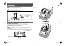
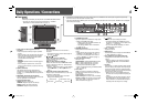
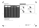
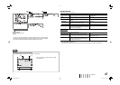
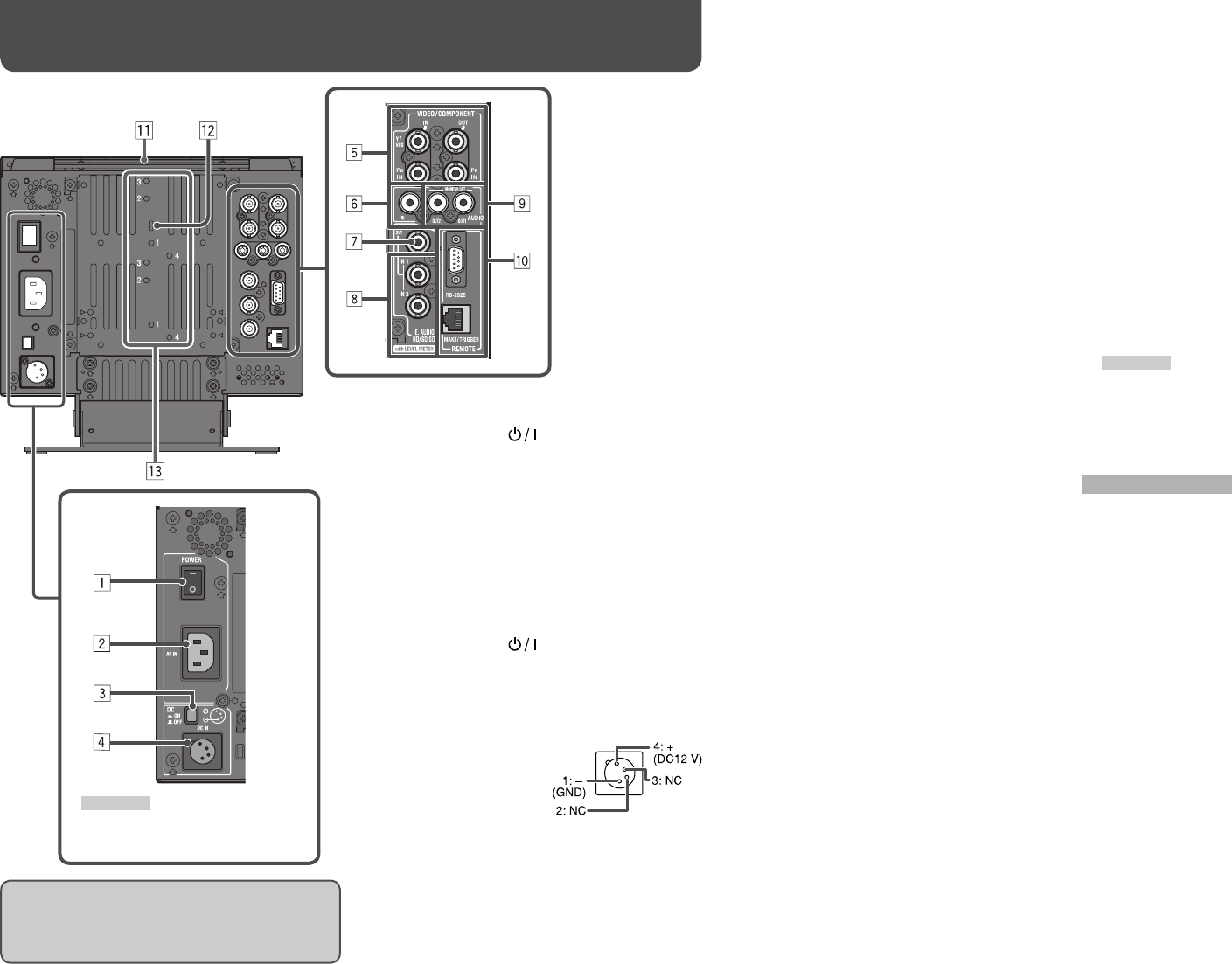
7 Rear panel
Daily Operations / Connections (cont.)
8
1 POWER switch
Turns AC power on or off.
• You need to press button (☞ w on page 6)
to use the monitor after turning on the POWER
switch.
2 AC IN terminal
AC power input connector.
Connect the provided AC power cord to an AC
outlet.
• Attach the provided power cord holder to prevent
accidental disconnection of the AC power cord (☞
“Attaching the Power Cord Holder” on page 9).
3 DC switch
Turns the DC 12 V power on or off.
• You need to press button (☞ w on page
6) on the front panel to turn on the monitor after
turning on the DC switch.
• The monitor consumes the battery even while the
monitor is on standby. To save battery life, turn
off the DC switch.
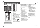
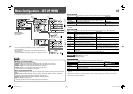
4 DC IN terminal
DC 12 V (maximum DC 17
V) power input connector.
• While using both the
AC and DC 12 V power
supply, AC power supply
is preferentially used. If the AC power supply is
cut off (for example, when turning off the POWER
switch), the power supply automatically switches
to the DC 12 V power supply.
5 VIDEO/COMPONENT terminals (BNC)
IN: Input terminals for the composite (VBS) and the
analog component (Y/P
B/PR) signals.
• Select the signal type in “VIDEO/COMPO. SEL.”
corresponding to the type of the input signal (☞
page 10).
OUT: Output terminal for the composite (VBS) and
the analog component (Y) signals.
6 AUDIO IN terminal (pin jack)
Input terminal for the analog audio signals.
• Use this terminal for the analog audio connection
of the SDI.
7 E. AUDIO HD/SD SDI (SWITCHED OUT) terminal
(BNC)
Output terminal for the HD/SD SDI signals.
• The SDI signals of the current input (SDI 1 or SDI
2) are re-clocked, then emitted.
• When an input other than SDI 1 and SDI 2 is
selected, the SDI signal of the input selected last
time is emitted from this terminal.
• The signals are emitted from this terminal only
when the monitor is on or in “P.SAVE” (power
save) mode.
8 E. AUDIO HD/SD SDI (IN 1, IN 2) terminals (BNC)
Input terminals for the HD/SD SDI signals.
• The terminals accept also EMBEDDED AUDIO
signals including up to 12 audio channels with a
sampling frequency of 48 kHz.
9 AUDIO (MONITOR OUT) terminals (pin jack)
Output terminals for the analog audio signal.
• The terminals emit the audio signals coming
in from the AUDIO IN terminal or EMBEDDED
AUDIO signals coming in from the E. AUDIO HD/
SD SDI (IN 1 or IN 2) input terminal. (☞ “Audio
Channel Selection” on page 7)
• The signal is output from these terminals only
when the monitor is on or in “P.SAVE” (power
save) mode. (☞ “NO SYNC ACTION” in “SYNC
FUNCTION” on page 13)
• The EMBEDDED AUDIO signal...
– is decoded into an analog signal, then emitted.
– is emitted only when “SDI 1” or “SDI 2” is
selected, and when EMBEDDED AUDIO
signals come in to the E. AUDIO HD/SD SDI
(IN 1 or IN 2) terminal.
When using DC 12 V power (maximum DC 17 V),
check the DC IN terminal pin signal, and use the
correct polarity. If the polarity is reversed, this
could cause a fire or personal injury.
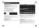
p REMOTE terminals
Terminals for controlling the monitor by an external
control. (☞ “External Control” on page 16)
q Carry handle
Use this handle when carrying the monitor.
w Security slot
Attach a security wire to this slot.
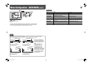
e Screw holes for external battery attachment
Attach external battery for DC 12 V power supply
by using 2 screw holes. Choose the appropriate
screw holes from 1, 2, 3 or 4, according to the type
of external battery.
• Use the Anton Bauer Dionic 90 (mount: QR DXC-
M3A) external battery.
CAUTION
• Do not use the external battery for DC 24 V
power supply.
• Use only the battery specified above. If a heavy
battery is used, it may fall off depending on the
way the monitor is used.
Note for connections
• Before making any connections, turn off all the
equipment.
• Use a cord whose plugs correctly match the
terminals on this monitor and the equipment.
• Plugs should be firmly inserted; poor connections
could cause noise.
• When unplugging a cord, be sure to grasp its plug
and pull it out.
• DO NOT connect the power cord until all connections
are complete.
• Refer also to the user manual of each piece of
equipment.
CAUTION
Do not connect the power cord until all
other connections are completed.
DT-V9L3D_EN.indd 8DT-V9L3D_EN.indd 8 09.7.23 10:33:55 AM09.7.23 10:33:55 AM