58
Specifications
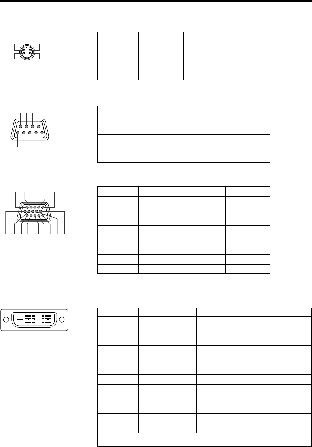
Pin arrangement
Ⅵ Y/C terminal
Ⅵ RS-232C IN/OUT terminal
Ⅵ PC 1 terminal
Ⅵ PC 3 terminal
4
2
9
8
16
8 7 6
54321
3
1
11 12 13
6712 1094538
1514
24
7
15
23
6
14
22
3
11
19
2
10
18
5
13
21
4
12
20
1
9
17
Pin number
1
2
3
4
Signal name
GND (Y)
GND (C)
Y
C
Pin number
1
2
3
4
5
Signal name
N/C
RD
TD
N/C
GND
Pin number
6
7
8
9
Signal name
N/C
N/C
N/C
N/C
N/C
Pin number
1
2
3
4
5
6
7
8
Pin number
9
10
11
12
13
14
15
Signal name
N/C
GND (SYNC)
GND
N/C
H.SYNC
V.SYNC
N/C
Signal name
Red
Green
Blue
N/C
N/C
GND (Red)
GND (Green)
GND (Blue)
Pin number
1
2
3
4
5
6
7
8
9
10
11
12
Signal name
TMDS data 2 -
TMDS data 2 +
TMDS data 2/4 shield
N/C
N/C
DDC clock
DDC data
N/C
TMDS data 1 -
TMDS data 1 +
TMDS data 1/3 shield
N/C
Pin number
13
14
15
16
17
18
19
20
21
22
23
24
Signal name
N/C
TMDS +5 V power supply
Earth (+5 V)
Hot plug detection
TMDS data 0 -
TMDS data 0 +
TMDS data 0/5 shield
N/C
N/C
TMDS clock shield
TMDS clock +
TMDS clock -
TMDS = Transition Minimized Differential Signaling
DDC = Display Data Channel
HX-1E_p50-61_En.p65 10/3/03, 6:11 PM58


