


NovaJet 500/630/700 Series Service Manual
ASSEMBLY/
DISASSEMBLY
Assembly\Disassembly 5-15
13. Connect the Power Supply connector to J15 on the MPCB.
14. Reinstall any additional memory into J17 by performing steps 1
and 2 of the Install Extra Memory (SIMM) procedure.
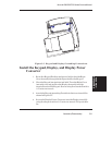
15. Perform steps 4 through 10 of the Install the Left, Top, and Right
Covers procedure to install the Right and Top Covers.
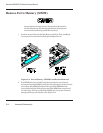
Remove Power Supply, Cooling Fan, and AC
Entry Module
NOTE
The following procedure covers items whose exact loca-
tion and/or appearance may differ then those shown in
the illustrations when refering to the NovaJet 750
printer.
1. Perform steps 1 through 9 of the Remove the Left, Top, and Right
Covers procedure to remove the Top and Right Covers.
2. Perform steps 3 through 15 of the Remove the MPCB (Main
Printed Circuit Board) procedure to remove and protect the
MPCB.
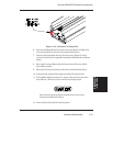
3. Reach between the Power Supply Bracket and the AC Entry
Module and carefully pull out the quick disconnect assembly
attaching the Power Supply input to the AC Entry Module.
Disconnect the Power Supply input from the AC Entry Module.
4. Disconnect the clip securing the power supply wires to the top of
the support bracket.
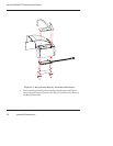
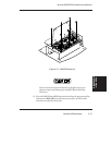
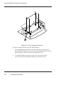
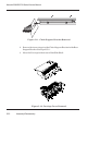
5. While holding the Power Supply in place, remove the four screws
securing it to the Power Supply Bracket. See Figure 5-8.
6. Slide the Power Supply out of the Power Supply Bracket.