


5-28 Assembly\Disassembly
NovaJet 500/630/700 Series Service Manual
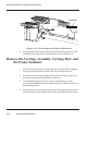
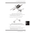
5. Slide the Carriage Assembly onto the left end of the Slide Shaft,
making sure that the Encoder Strip fits into the slot in the Slider
and the Encoder on the Carriage PCB. Guide the belt while sliding
the Carriage Assembly from left to right on the Slide Shaft.
6. Move the Carriage Assembly to the left end of the Slide Shaft and
align the left bushing on the Carriage Assembly with the left end of
the Slide Shaft.
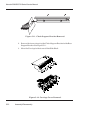
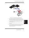
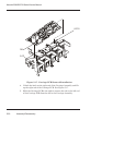
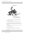
7. Insert the Strain Relief (with Trailing Cable) onto the Carriage
Assembly by sliding it onto the Strain Relief Support until it snaps
firmly into place. See Figure 5-15.
8. Place the Trailing Cable into the J1 connector lock on the Carriage
PCB. Make sure the silver fingers on the Trailing Cable are fully
inserted into the lock and slide both sides of the connector lock shut
at the same time.
9. Place the right side of the back of the Electronics Cover under the
Trailing Cable Support Assembly and gently press down on the ends
of the Electronics Cover until the latches snap into the Carriage
Assembly.
10. Slide the Carriage Assembly to about the middle of the Slide Shaft
and stretch out the Carriage Belt.
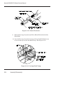
11. Insert the Carriage Belt into the Frame Tensioner so that the belt
extends about an inch past the Frame Tensioner.
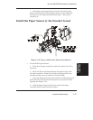
12. Holding the Carriage Belt and Frame Tensioner, insert the Idler
Pulley Assembly into the loop of the belt. Make sure that the side of
the Idler Pulley Assembly with the thicker outer ring of plastic is
facing up. See Figure 5-15.
13. Once the Idler Pulley Assembly is in position, pinch the belt to hold
the Idler Pulley Assembly in place and pull it into the Frame
Tensioner so that the axle rests in the V-shaped groove in the
Frame Tensioner.
14. Insert the Compression Spring into the opening in the back of the
Frame Tensioner so that the end of the spring fits over the post
inside the opening.