KRAMER: SIMPLE CREATIVE TECHNOLOGY
Overview
6
3.2 Connecting the VP-23RC Rear Panel
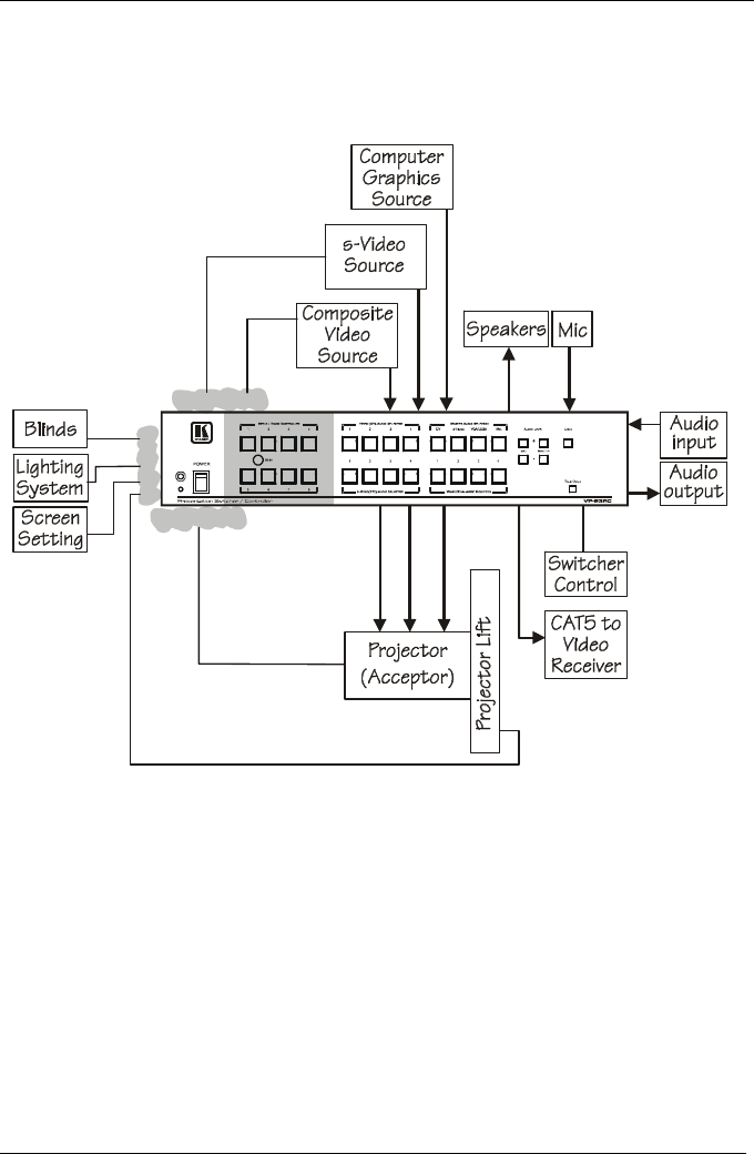
The VP-23RC can be connected in different configurations, integrating the
Presentation Switcher section with the Media/Room Controller section. The
block diagram in Figure 1 shows a VP-23RC configuration example:
IR Emitters
Relays
RS-232
Figure 1: VP-23RC Configuration Example
In this example:
Three VIDEO sources are connected to the inputs
The three VIDEO outputs are all connected to the same projector
The projector is connected to the RS-232 port in the CONTROLLER area
Two of the video sources are also connected to the IR terminal blocks
A CAT 5 UXGA receiver is connected
Various room items are connected to the RELAY terminal blocks
A microphone and speakers are connected, as well as the audio inputs and
outputs


