


12 3: Monitoring the 4092A
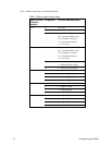
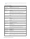
Table 1 defines each status or alarm bit position.
Table 1: Status or alarm binary codes
Status or alarm
character
position
Bit position Bit value and description
a or f 19 Not used
18 Not used
16 and 17 Remote control bits:
0:0 = Autoswitch/don’t care
0:1 = Channel A selected
1:0 = Channel B selected
1:1 = Not used
b or g 15 and 14 Front panel switch control bits:
0:0 = Autoswitch/don’t care
0:1 = Channel A selected
1:0 = Channel B selected
1:1 = Not used
13 0 = Channel A active input
1 = Channel B active input
12 1 = Cannot lock to input B
c or h 11 1 = Cannot lock to input A
10 1 = Autoswitch occurred
9 1 = Power supply 2 fault
8 1 = Power supply 1 fault
d or i 7 1 = output 8 failed
6 1 = output 7 failed
5 1 = output 6 failed
4 1 = output 5 failed
e or j 3 1 = output 4 failed
2 1 = output 3 failed
1 1 = output 2 failed
0 1 = output 1 failed