


4092A Operations and Maintenance Manual 25
Appendix A: Specifications
A.3 Electrical Specifications
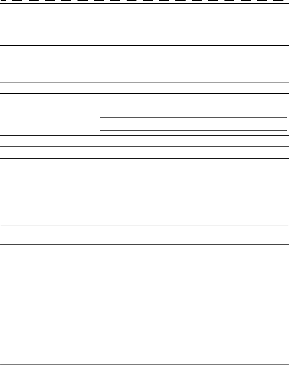
Table 3 lists the electrical specifications for the 4092A.
Table 3: Electrical specifications
Item Specification
Protection Class Class I (Grounded Type)
Power Input Voltage 100–240 V ~ 50/60 Hz 0.5 A, power dissipation ~20 Watts
Note: Fluctuations not to exceed ± 10% of nominal supply voltage.
Power Inlet Type IEC 60320 sheet C14
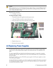
AC Power Supply Cord Set
18 AWG (0.75 mm
2
minimum)
DC Power Supply The external wiring to this connector must be at a minimum 1.5 mm² (14 AWG)
with a 15 A fuse or circuit breaker. A 20 A circuit breaker may be used if the
external wiring is jacketed 14 AWG, with maximum length of 20 feet. An
internal fuse mounted on the power supply carrier board is included to protect
this input but is not field replaceable. Mating connector for the DC power
supply is a AMP 1-350344-0 and 2 sockets are required, AMP 350388-1.
Power Supply Part Numbers AC: TSC 4501A
DC: TSC 4502A
Power Mains Fuse AC: (2) - 250V~1A time lag 5 x 20 mm. Initial shipments will have one fuse.
DC: No customer-serviceable fuses.
Unmodulated Signal Input
Frequency: 1–200 kHz
Lo-Z Impedance: 50 Ω ±5 Ω
Hi-Z Impedance: 600 Ω ±10 Ω
Input level: > 1.5 V peak to peak into 50 Ω
Modulated Signal Input
Code Format: IRIG-B
Frequency: 1 kHz (IRIG-B)
Lo-Z Impedance: 50 Ω ±5 Ω
Hi-Z Impedance: 600 Ω ±10 Ω
Input level: > 2.8 V peak to peak into 50 Ω
Connectors
Input: 2 BNC
Output: 8 BNC
LAN: RJ-45
Gain 0 dB
Isolation > 70 dB