


2-1
2: Installation
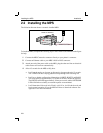
This chapter describes the various MPS models and shows how to install them into a
basic network situation.
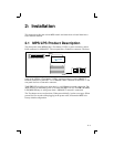
2.1 MPS/LPS Product Description
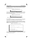
The front panel of the MPS100 has a Test button, 3 LEDs, a power connector, and an
RJ45 connector for 100BASE-T. The rear panel has a Centronics connector. The front
panel of the LPS has a Test button, 2 LED’s, a power connector, and a 10BASE-T
network connector for the LPS1-T or a 10BASE-2 BNC connector for the LPS1-2. The
rear panel also has a Centronics connector.
The LINK LED is solid green when there is a valid Ethernet network connection. The
ACT (Activity) LED flashes green or red when the MPS is in use. The 100 (100 MBit)
LED (MPS100 only) is solid green when a 100BASE-T network is connected.
The Test button serves two functions. When pressed briefly, it prints a test page. When
pressed for five seconds while plugging in the power cable, it returns the MPS to its
factory default configuration.
TEST
LINK
5VDC
AC
T
100
Centronics Connector
“front”
“back”