


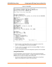
UDS10/UDS100 User Guide Configuring the UDS Using Telnet or the Serial Port
27
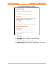
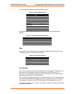
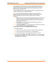
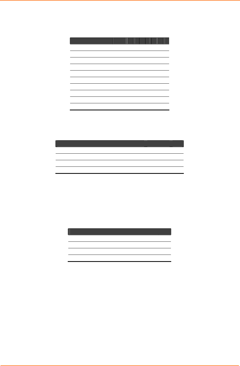
The following table displays available I/F Mode options:
Table 5-3. Interface Mode Options
I/F Mode Option Bit 7 6 5 4 3 2 1 0
RS-232C 0 0
RS-422/485 0 1
RS-485 2-wire 1 1
7 Bit 1 0
8 Bit 1 1
No Parity 0 0
Even Parity 1 1
Odd Parity 0 1
1 Stop bit 0 1
2 Stop bit
1
1
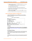
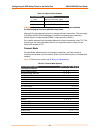
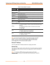
The following table demonstrates how to build some common Interface Mode
settings:
Table 5-4. Common Interface Mode Settings
Common I/F Mode Setting Binary Hex
RS-232C, 8-bit, No Parity, 1 stop bit 0100 1100 4C
RS-232C, 7-bit, Even Parity, 1 stop bit 0111 1000 78
RS-485 2-Wire, 8-bit, No Parity, 1 stop bit 0100 1111 4F
RS-422, 8-bit, Odd Parity, 1 stop bit 0101 1101 5D
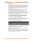
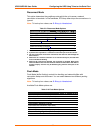
Flow
Flow control sets the local handshake method for stopping serial input/output. Use
the following table to select flow control options:
Table 5-5. Flow Control Options
Flow Control Option Hex
No flow control 00
XON/XOFF flow control 01
Hardware handshake with RTS/CTS lines 02
XON/XOFF pass characters to host 05
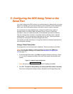
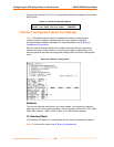
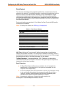
Port Number
Every TCP connection and every UDP datagram has a destination IP address and a
port number. A port number is similar to an extension on a PBX system. For
example, a Telnet application commonly uses port number 23. Port number 9999 is
reserved for access to the unit's Setup Mode.
The Port Number setting represents the source port number in TCP connections. It is
the number that identifies the channel for remote initiating connections. For example,
to send data to channel 1, send TCP/UDP packets to this assigned port number.
The default setting for port 1 is 10001. The range is 1-65535, except for the following
reserved port numbers: