


UDS10/UDS100 User Guide
6
Network Port ___________________________________________________ 53
Ethernet Connector Pinouts _______________________________________ 54
10: Technical Specifications 55
UDS10 Technical Specifications _______________________________________ 55
UDS100 Technical Specifications ______________________________________ 56
A: Alternative Ways to Assign an IP Address 57
DHCP ________________________________________________________ 57
AutoIP ________________________________________________________ 57
BOOTP _______________________________________________________ 58
ARP and Telnet_________________________________________________ 58
B: Binary to Hexadecimal Conversions 59
Converting Binary to Hexadecimal______________________________________ 59
Conversion Table _______________________________________________ 59
Scientific Calculator______________________________________________ 60
Connect Mode Options ______________________________________________ 61
Disconnect Mode Options ____________________________________________ 64
Flush Mode Options_________________________________________________ 66
Interface Mode Options ______________________________________________ 72
Pack Control Options________________________________________________ 73
Declaration of Conformity 75
Warranty 76
Index 77
Figures
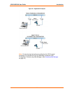
Figure 2-1. Application Examples ________________________________________ 11
Figure 2-2. Sample Ethernet Address _____________________________________ 13
Figure 3-1. UDS Connected to Serial Device and Network _____________________ 14
Figure 4-1. Web Browser Login __________________________________________ 18
Figure 4-2. UDS Configuration Guidelines Page _____________________________ 19
Figure 4-3. Lantronix Web Manager ______________________________________ 20
Figure 4-4. Server Properties Configuration on the Web Browser________________ 21
Figure 5-1. Network Login Using Telnet____________________________________ 22
Figure 5-2. Setup Mode ________________________________________________ 23
Figure 5-3. Network Configuration________________________________________ 24
Figure 5-4. Server Configuration Option ___________________________________ 26
Figure 5-5. Channel 1 Configuration ______________________________________ 26
Figure 5-6. Hostlist Option ______________________________________________ 30
Figure 5-7. Expert Settings Options_______________________________________ 35
Figure 5-8. Security Settings ____________________________________________ 36
Figure 6-1. TFTP Dialog Box ____________________________________________ 41
Figure 6-2. Sending Firmware to Another Unit_______________________________ 41
Figure 6-3. Firmware Upgrade Screen Display ______________________________ 42
Figure 7-1. Entering Monitor Mode Using the Network ________________________ 43
Figure 9-1. Serial Interface _____________________________________________ 51
Figure 9-2. DB25 Female DCE Interface RS232_____________________________ 52
Figure 9-3. DB25 Female DCE Interface RS485/422 _________________________ 52