


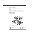
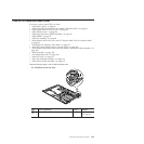
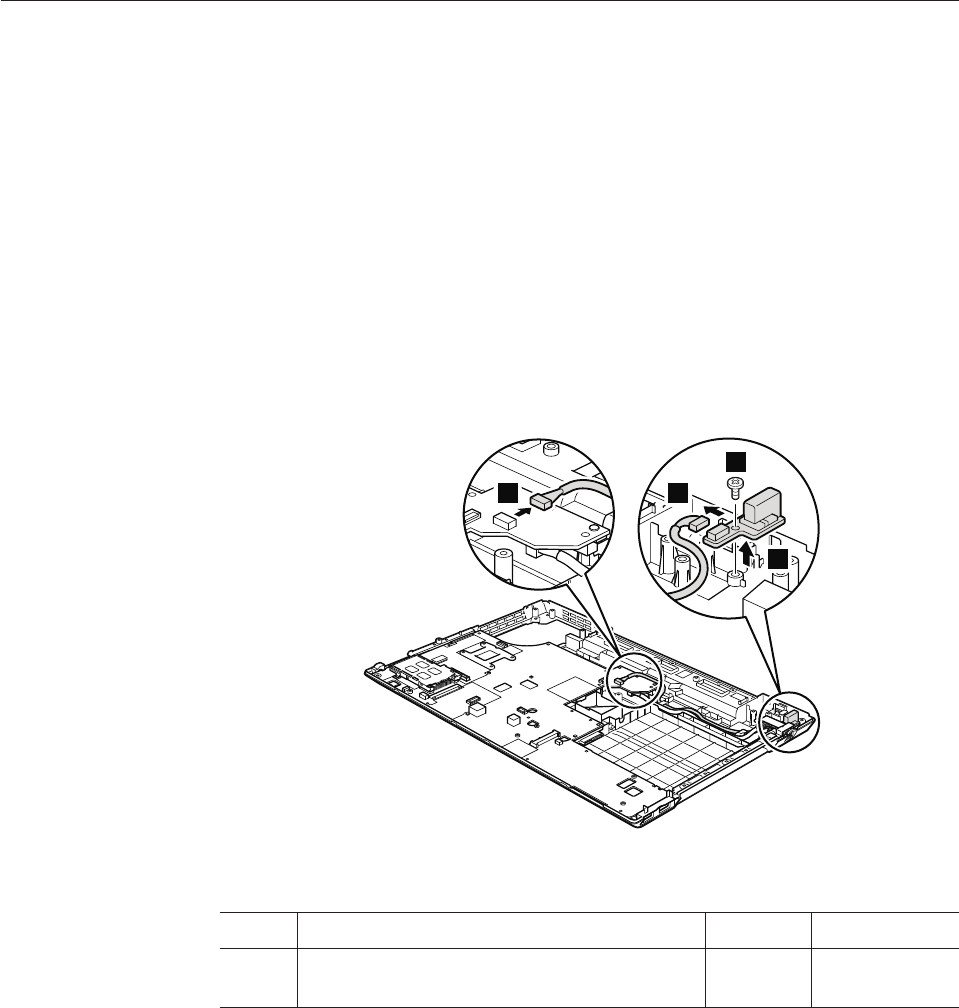
1210 USB connector board and USB cable assembly
For access, remove these FRUs in order:
v “1010 Battery pack” on page 80
v “1040 Thermal cover” on page 84
v “1050 Hard disk drive (HDD) assembly” on page 85
v “1100 Wireless WAN slot cover and PCI Express Mini Card for wireless WAN”
on page 95
v “1110 Palm rest assembly with cables” on page 97
v “1120 PCI Express Mini Card for wireless LAN” on page 100
v “1150 Media Card Reader slot board and Media Card Reader cable assembly” on
page 104
v “1160 Keyboard” on page 106
v “1170 Keyboard bezel” on page 109
v “1180 LCD unit” on page 111
v “1190 Top shielding assembly” on page 116
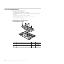
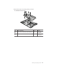
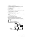
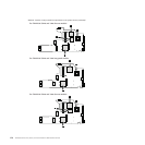
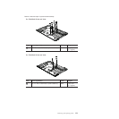
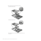
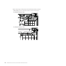
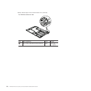
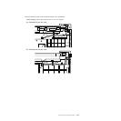
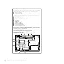
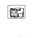
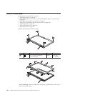
Table 32. Removal steps of USB connector board and USB cable assembly
3
2
4
1
When installing: Make sure that the connectors are attached firmly.
Step Screw (quantity) Color Torque
2 M2 × 3 mm, wafer-head, nylon-coated (1) Black 0.167 Nm
(1.7 kgfcm)
Removing and replacing a FRU 123