


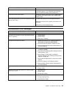
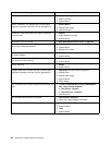
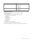

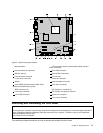
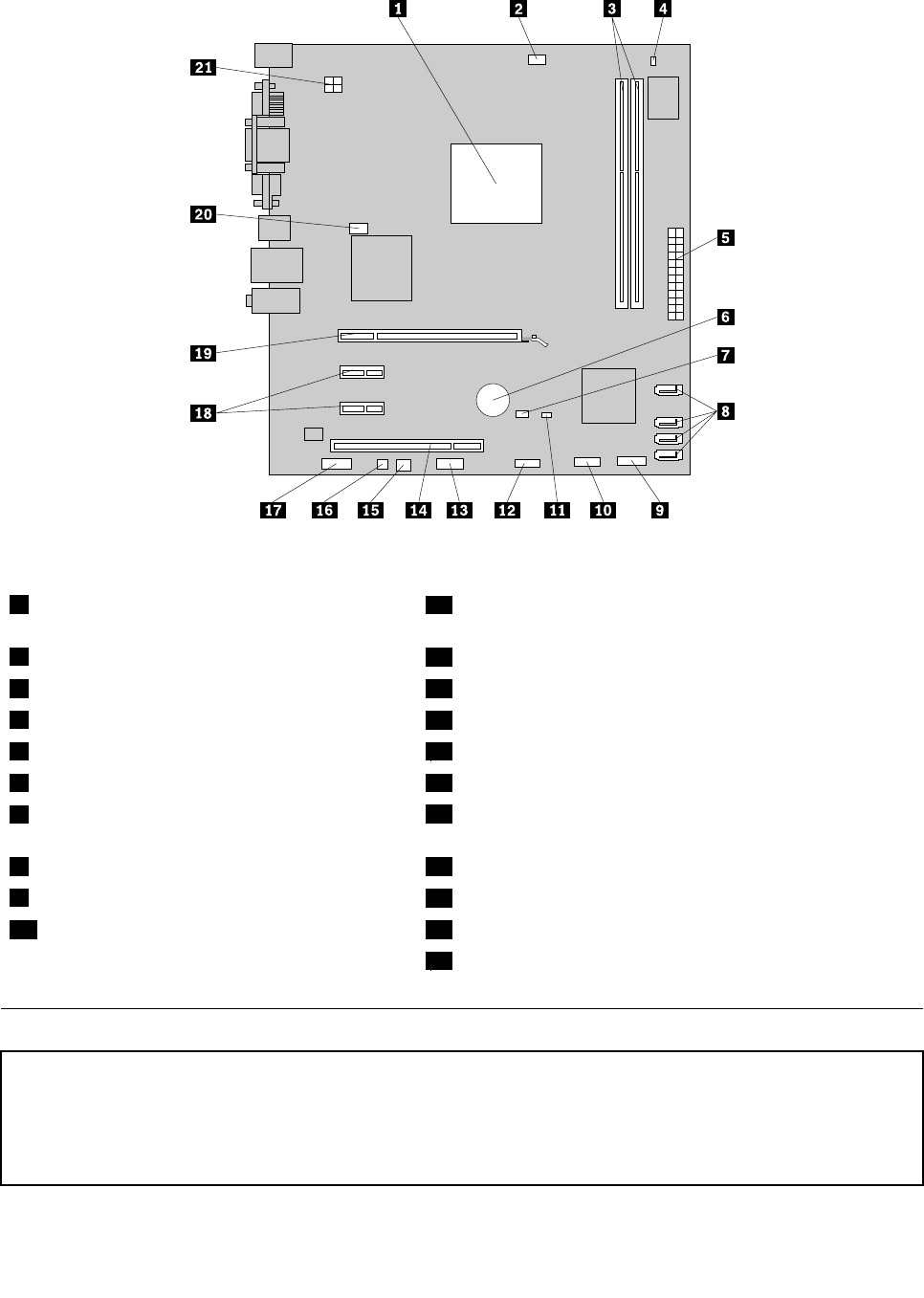
Figure 5. System board part locations
1 Microprocessor
11 Cover presence switch connector(also called intrusion
switch connector)
2 Microprocessor fan connector
12 Front USB connector
3 Memory slots (2) 13 Serial (COM 2) connector
4 Thermal sensor connector
14 PCI card slot
5 24-pin power connector
15 Power fan connector
6 Battery 16 Internal speaker connector
7 Clear CMOS (Complementary Metal Oxide
Semiconductor)/Recovery jumper
17 Front audio connector
8 SATA connectors (4) 18 PCI Express x1 card slots (2)
9 Front panel connector
19 PCI Express x16 graphics card slot
10 Front USB connector 20 System fan connector
21 4-pin power connector
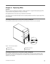
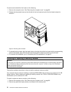
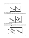
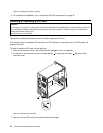
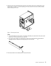
Removing and reinstalling the front bezel
Attention
Do not open your computer or attempt any repair before reading and understanding the “Important safety information”
in the ThinkCentre Safety and Warranty Guide that came with your computer. To obtain a copy of the ThinkCentre
Safety and Warranty Guide, go to:
http://www.lenovo.com/support
This section provides instructions on how to remove and reinstall the front bezel.
Chapter 8. Replacing FRUs 71