


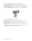
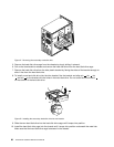
Figure 17. Removing the microprocessor
9. Make sure that the small handle is in the raised position.
10. Remove the protective cover that protects the gold contacts on the new microprocessor.
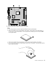
11. Hold the new microprocessor and align the small triangle on one corner of the new microprocessor with
the corresponding small triangle on one corner of the microprocessor socket.
12. Lower the new microprocessor straight down into the microprocessor socket on the system board.
13. Lower the small handle to secure the new microprocessor in the socket.
14. Reinstall the heat sink and fan assembly. See “Replacing the heat sink and fan assembly” on page 78.
15. Reinstall any other parts or reconnect any other cables you removed.
16. Go to “Completing the FRU replacement” on page 97.
Replacing the system board
Attention
Do not open your computer or attempt any repair before reading and understanding the “Important safety information”
in the ThinkCentre Safety and Warranty Guide that came with your computer. To obtain a copy of the ThinkCentre
Safety and Warranty Guide, go to:
http://www.lenovo.com/support
This section provides instructions on how to replace the system board.
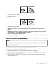
CAUTION:
The heat sink and microprocessor might be very hot. Turn off the computer and wait
three to ve minutes to let the computer cool before removing the computer cover.
Note: When replacing the system board, you must order a new retention module for the new system board.
Make sure you have a retention module for the new system board before continuing this procedure.
To replace the system board, do the following:
1. Remove the computer cover. See “Removing the computer cover” on page 68.
2. Remove the primary hard disk drive with the hard disk drive cage. See “Replacing the primary hard
disk drive” on page 83.
3. Lay the computer on its side to make the system board more accessible.
4. Remove all memory modules and PCI cards that are currently installed. See “Installing or replacing a
memory module” on page 72 and “Installing or replacing a PCI card” on page 74.
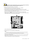
5. Carefully take note of the location of all cable connectors on the system board and disconnect all the
cables. See “Locating parts on the system board” on page 70.
6. Remove the heat sink and fan assembly from the failing system board. See “Replacing the heat sink and
fan assembly” on page 78
.
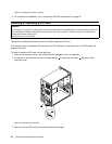
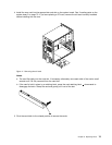
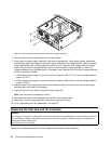
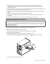
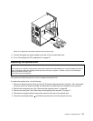
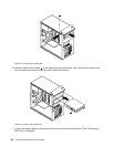
7. Remove the screws that secure the system board to the chassis.
8. Carefully remove the system board out of the chassis.
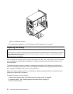
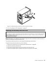
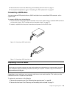
9. Remove the microprocessor from the failing system board and install it on the new system board.
See “Replacing the microprocessor” on page 80
.
10. Install the new retention module on the new system board.
82 ThinkCentre Hardware Maintenance Manual