


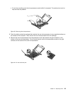
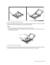
12. Carefully lift the failing system board out of the chassis.
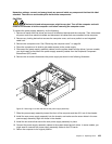
13. Position the new system board into the chassis so that the screw holes in the new system board are
aligned with those in the chassis. Install the ten screws that secure the system board to the chassis by
following the sequence from 10 to 1 .
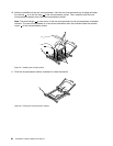
14. Remove the microprocessor socket cover(s) from the new system board.
15. Install the memory modules, PCI cards, battery, microprocessor, heat sink and fan assembly, hard disk
drive enablement module (if applicable), and the hard disk drive fan assembly that you removed from the
failing system board to the new system board.
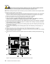
16. Connect all cables to the system board. See “Locating parts on the system board” on page 58.
17. Go to “Completing the parts replacement” on page 104.
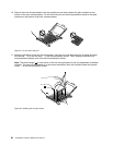
The failing system board must be returned with microprocessor socket covers to protect the pins during
shipping and handling. Install the microprocessor socket covers removed from the new system board
on the failing system board.
Note: The microprocessor socket cover installation procedure should be performed on both microprocessor
sockets on the failing system board.
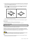
To install the microprocessor socket cover on the failing system board:
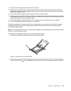
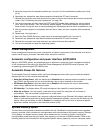
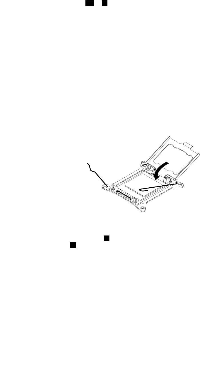
1. Pivot the microprocessor retainer downward to close the retainer.
Figure 52. Closing the microprocessor retainer
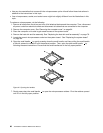
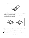
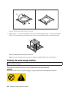
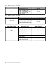
2. Gently press down the small handle 1 , and then push the handle inward to secure it. Then gently press
down the small handle 2 and push the handle inward to lock the microprocessor retainer into position.
Chapter 10. Replacing FRUs 101