


Installation
9
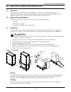
3.4 External Electrical Connections
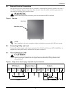
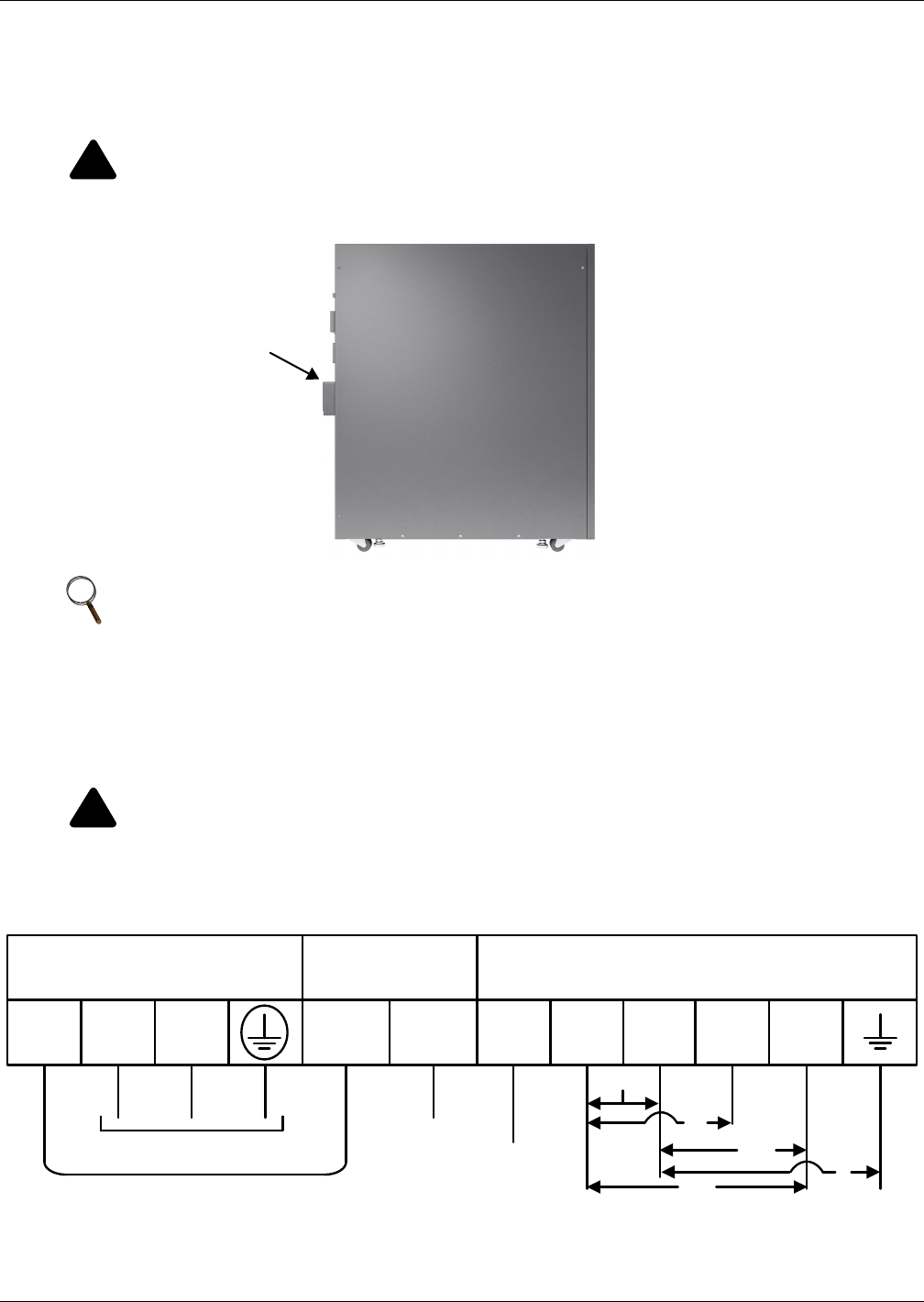
The external electrical connections may be accessed by removing the protective panel on the rear of
the UPS (see Figure 2) (panel ships loose from factory). Select a conduit knockout appropriate for
your cabling, based on local electrical codes.
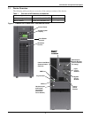
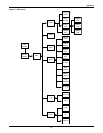
Figure 4 Side view
3.5 Connecting Utility and Load
Connect the utility supply to the input terminals of the UPS. If the Liebert
®
GXT3-10000T220
™
is
supplied by single-phase utility, connect the live phase to input L1.
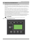
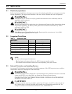
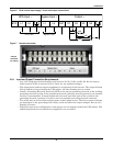
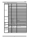
3.6 Terminal Blocks for UPS
Figure 5 Single source input supply—input and output connections
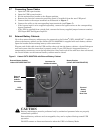
!
WARNING
Before removing electric protective panel, ensure that the UPS is isolated.
NOTE
Once installation has been completed, adjust leveling feet to prevent the UPS from moving.
!
CAUTION
Power is connected through the input breaker, even when the UPS is in bypass mode.
Opening the input breaker when in bypass mode will disconnect output power to the
connected load.
Rear Panel
Cable Entry Cover
L1 L2 GET X1 X2
UPS Input ~ Output ~
BYP L1 L2
Bypass Input ~
X4X3
Single Feed
Jumper
120
208
220
120
0
240