


Installation
10
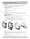
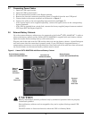
Figure 6 Dual source input supply—input and output connections
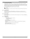
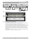
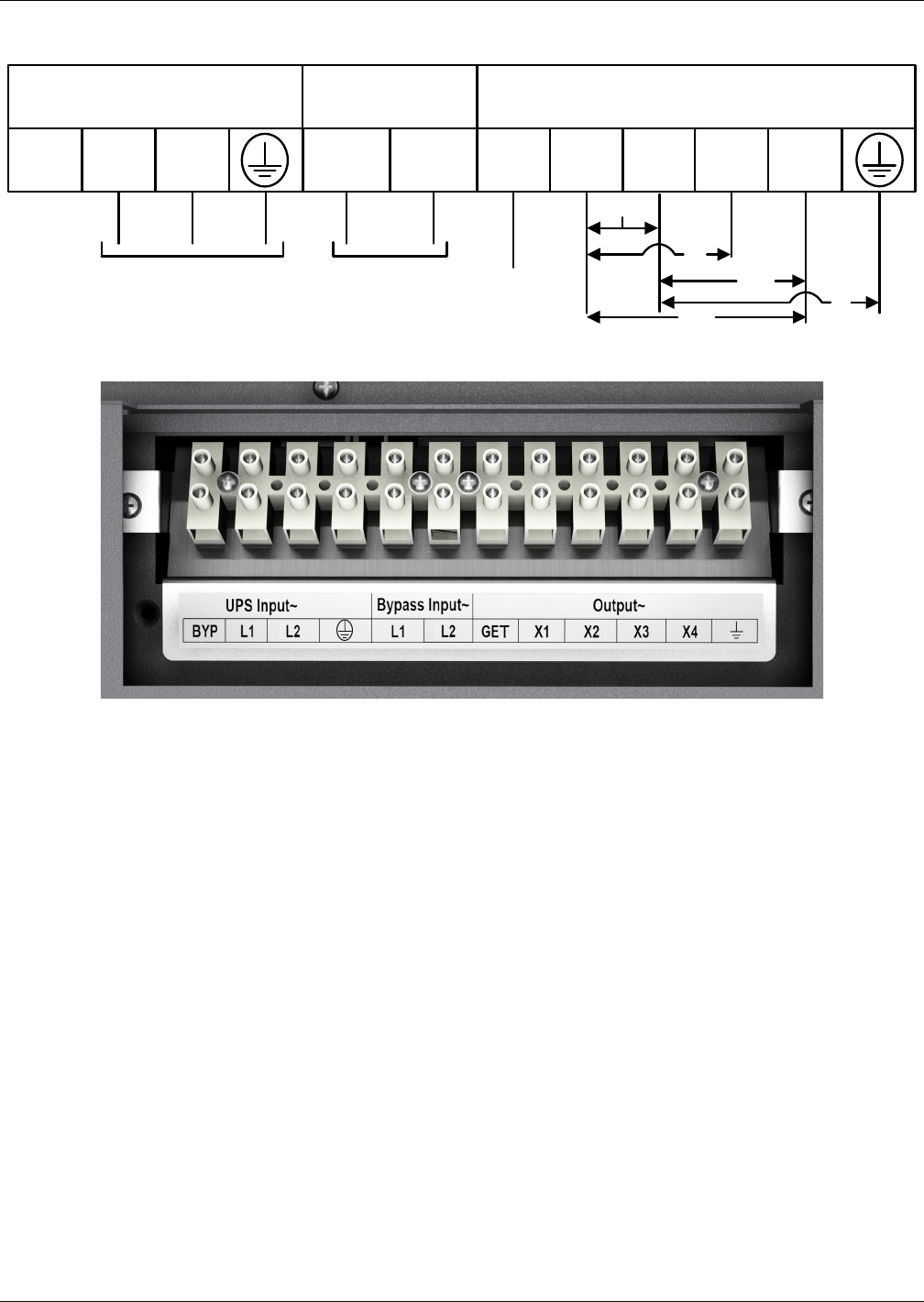
Figure 7 Hardwire terminals
3.6.1 Input and Output Connection Requirements
• Any 120V loads must be distributed evenly between X1-X2, X1-X4 and X4-X2. Do not connect
loads between X3-X2 or between X3-X4—these are not standard voltages.
• The single-phase isolation output transformer is a separately derived source. The output Neutral
(X2) is bonded to Ground within the UPS cabinet. No other bonding wire is needed.
• Install a Grounding Electrode Terminal (GET) to the nearest grounding electrode in the building
grounding electrode system. If the grounding electrode conductor must be protected, non-metallic
conduit is recommended. If metal conduit must be used, bond both ends of the conduit to the
grounding electrode conductor. Conduit is not an acceptable grounding electrode conductor.
• The utility may be derived from a single-phase or three-phase source. The line-to-ground voltages
are dependent on the grounding of the utility and do not affect the output voltages. Do not use a
floating AC source.
• With dual input source configuration, both sources are tied together within the UPS cabinet. Two
additional ground screw terminals are supplied for use as needed.
L1 L2 GET X1 X2
UPS Input ~ Output ~
BYP L1 L2
Bypass Input ~
X4X3
UPS Feed
120
208
220
120
0
240
Bypass Feed
Jumper
removed
for clarity