


Introduction
7
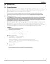
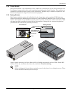
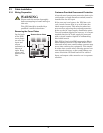
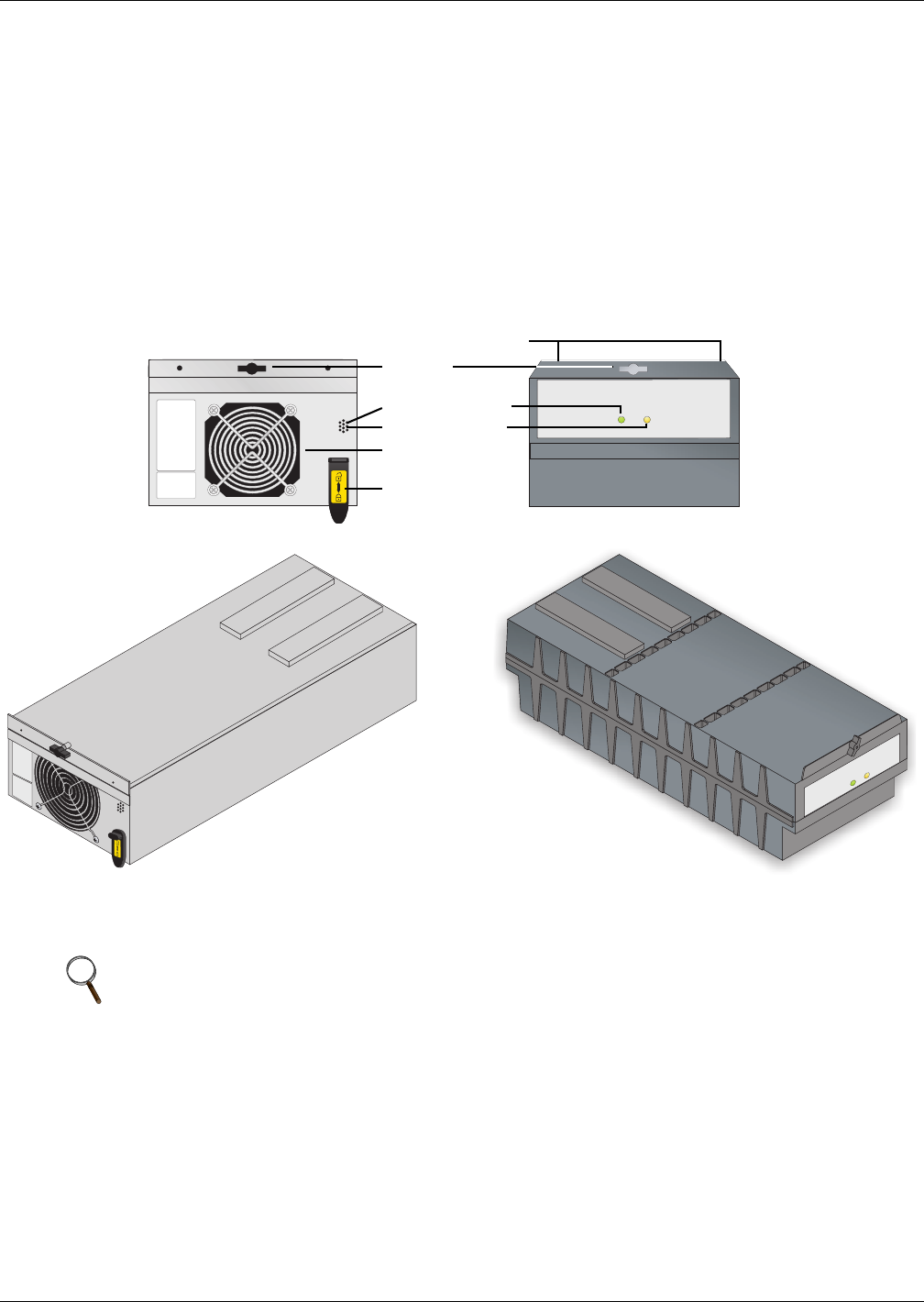
1.3.4 Power Module
Each power module is an independent 4 kVA, 2.8kW unit, consisting of a power factor corrected recti-
fier, battery charger and inverter, with associated monitoring and control circuitry. The modules are
paralleled to provide greater capacity and/or redundancy. Modules may be added or replaced on-line
with no interruption or danger to the connected equipment.
1.3.5 Battery Module
Each battery module contains 10 individual 12-volt, 9 amp hour, valve-regulated (VRLA) battery
blocks with associated monitoring and controls to isolate the Battery Module in the event of a battery
failure. The modules are paralleled to provide greater capacity, backup time and/or redundancy. Mod-
ules may be added or replaced on-line with no interruption or danger to the connected equipment,
provided that the UPS is not operating on battery.
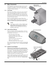
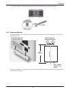
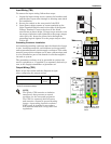
Under normal operation, the Green Status LED will blink continuously and the Yellow Fault LED
will be off. For any condition other than this, check 4.0 - Troubleshooting.
NOTE
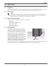
Nfinity is shipped with each battery module secured to the frame by two shipping screws. These
screws should be removed prior to start-up.
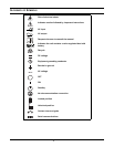
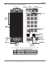
Power Module Battery Module
Shipping screws
FRONTFRONT
Fastener
Green Status LED
Yellow Fault LED
Cooling Fan
Lever