


Operating Instructions
17
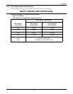
3.0 OPERATING INSTRUCTIONS
3.1 Controls and Indicators
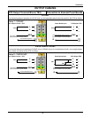
3.1.1 Display Controls
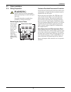
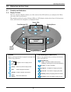
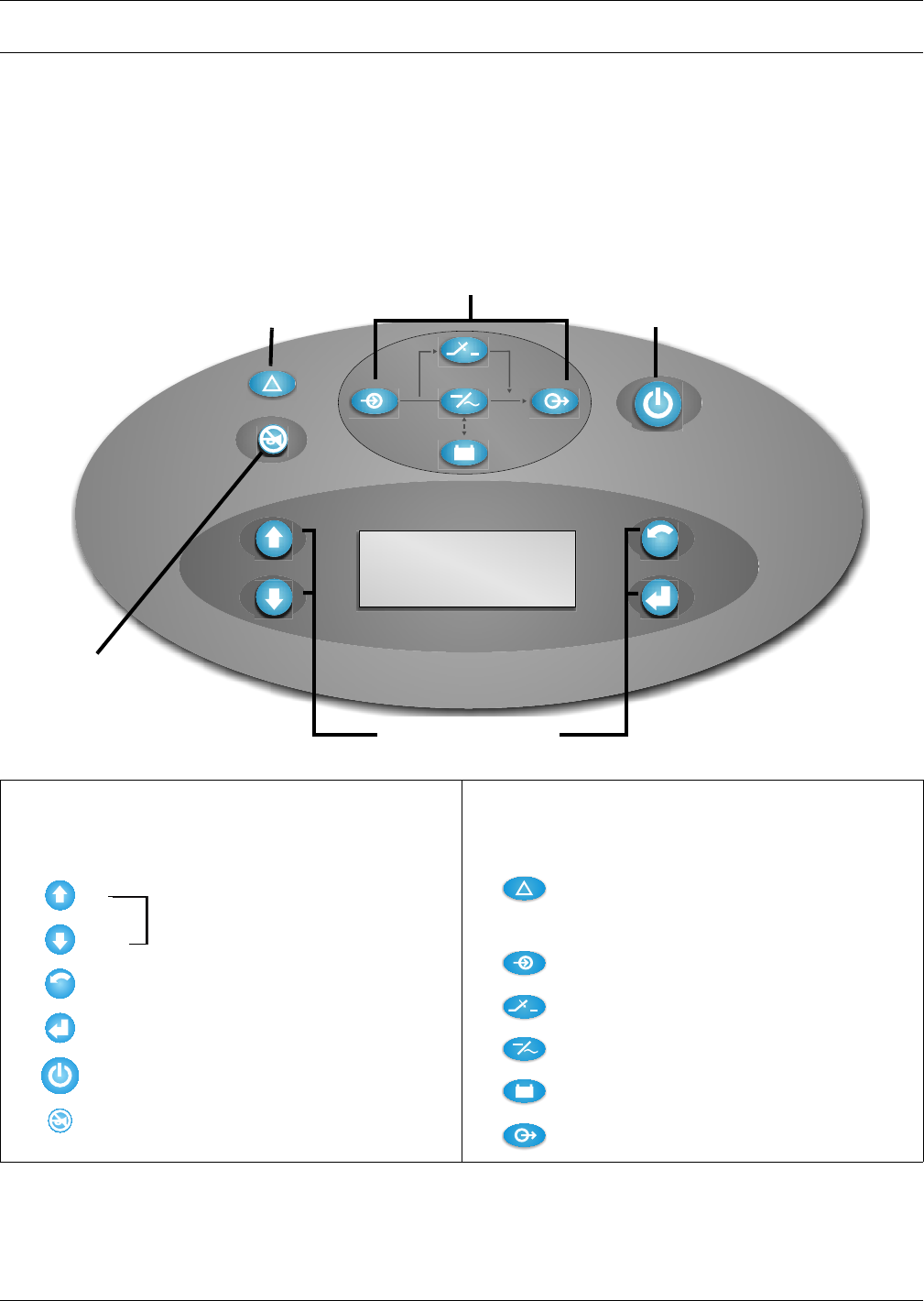
The User Interface Module informs you of the status of the UPS and lets you configure the UPS to
your own needs or preferences.
The module consists of a series of Status LEDs, an LCD display window (four lines of 20 characters
each), and buttons for navigation, as displayed below.
Buttons
Refer to the legend below to properly navigate the
Nfinity User Interface.
Fault/Warning and Status LEDs
Refer to the legend below to indicate occurrence
when an LED is lit.
LCD Display
Window
Standby Button
Alarm
Silence
Button
Fault/Warning LED
Status LEDs
Navigation Buttons
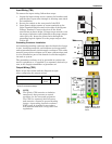
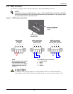
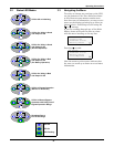
ESC
- Navigates cursor on display menus
- Returns to previous display screen
- Selects displayed information
- Enables / disables output power
- Mutes the audible alarm
Up
Down
Escape
Enter
Standby
Alarm
Silence
ESC
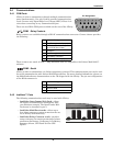
On Bypass - The Bypass is supplying the power.
Solid - A UPS fault condition has occurred.
Fault/Warning
AC Input - AC utility is available.
Inverter On - The inverter is supplying the power.
On Battery - Battery is supplying power to the inverter.
AC Output - Power is available to supply the load.
Flashing - A Warning has occurred. Consult event log.