Troubleshooting
35
4.3.2 Adding or Replacing Modules
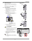
1. Lift module to appropriate bay, resting end of module on bay
shelf. Use caution not to rest the module on the lower bezel
cover.
2. Push module into bay. Once halfway in, slide module sideways
toward the center of the UPS. Continue pushing module until
fully inserted.
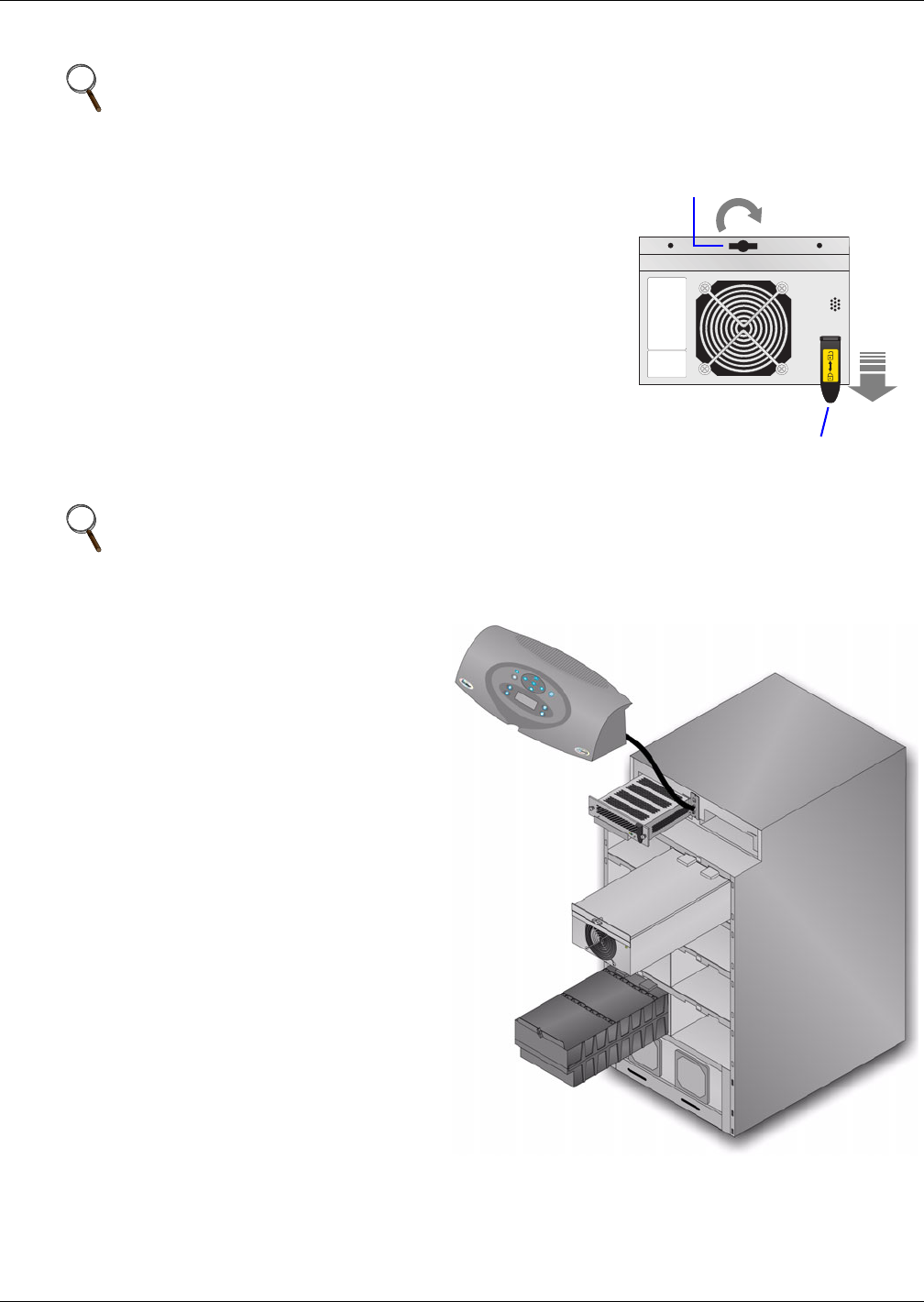
3. Press and turn fastener clockwise until locked. If replacing a
Control or Power Module, press lever down.
4. Wait about 15 seconds as the module performs a start-up test
and synchronizes with the other modules. Both the yellow and
green LEDs should be flashing. A green flashing LED will
then confirm the module is properly installed.
5. If UPS was placed in bypass manually, transfer back to UPS
operation.
6. Replace bezels.
4.3.3 Replacing the User Interface
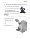
1. Lift off user interface and set it on top
of the UPS frame.
2. The attached cable will be connected to
an Intellislot card, found in a port
between the control modules.
3. Remove the cable and the attached
Intellislot card from the UPS.
4. Plug the new Intellislot card into the
UPS.
5. Plug the new user interface cable into
the Intellislot card.
6. Set replacement User Interface into
proper position.
NOTE
Power Modules must be installed in the top half of the Nfinity frame. Battery Modules can be
installed in any bay of the UPS frame.
NOTE
When replacing the Control Module, record user configuration data before removing. Re-verify
the configuration settings after the new Control Module is installed.
Turn fastener
clockwise
Press lever down (for
Control and Power Modules)


